Support-shaped jet type oil mixing device

A jetting, oil mixing technology, applied in mixers, mixers, fluid mixers, etc. with rotary stirring devices, can solve the problem of inconsistent oil technical quality indicators, limited power of the storage tank drive system, design and installation process Complex problems, to achieve the same technical quality indicators of oil products, ensure the effect of mechanical stirring, and increase the effect of mechanical stirring methods

Inactive Publication Date: 2016-06-29
QINZHOU UNIV
View PDF6 Cites 3 Cited by
  • Summary
  • Abstract
  • Description
  • Claims
  • Application Information

AI Technical Summary

Problems solved by technology

The oil storage device is equipped with discharge and discharge pipes so that the oil is in a dynamic flow to achieve mixing, which is low in cost and has no potential safety hazards, but there are still the following defects: First, the power of the drive system of the storage tank is limited, and it can only be stirred and discharged. For the oil products on the same level of the branch pipe and discharge branch pipe, the oil products in the tank can only undergo a small degree of laminar flow diffusion, resulting in low mixing uniformity of the oil products, so that the technical quality indicators of the upper, middle and lower oil products in the tank are inconsistent. There are many branch pipes, and the design and installation process are relatively complicated; secondly, the storage tank is not equipped with a stirring device, but the physical mixing of oil products is realized through the dynamic flow of downward suction and upper discharge countercurrent, and the single oil mixing method leads to uneven mixing. and low mixing efficiency

Method used


Image

  • Support-shaped jet type oil mixing device
  • Support-shaped jet type oil mixing device
  • Support-shaped jet type oil mixing device

Examples


Embodiment Construction

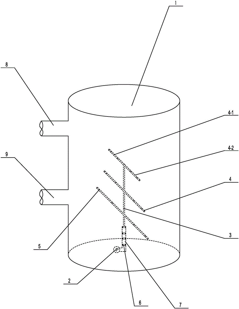
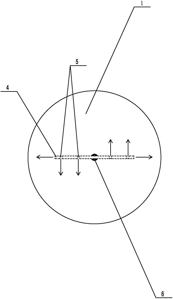
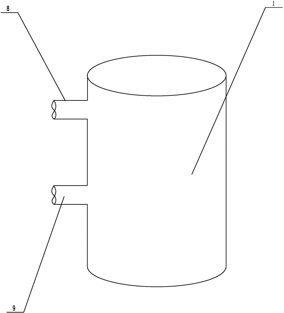
[0026] Such as figure 1 with figure 2 Propose a kind of specific embodiment of the present invention as shown, a kind of support-like jet oil mixing device, comprise tank body 1, the upper end of this tank body 1 outer wall is provided with oil inlet pipe 8, and the lower end is provided with oil outlet pipe 9, and described tank The bottom of the body 1 is provided with an explosion-proof servo submersible pump 2. The submersible pump 2 is connected to an external power supply through an explosion-proof power cord, and the output power is adjusted by frequency conversion. The submersible pump 2 is connected to a vertically installed The delivery pipe 3, the delivery pipe 3 is provided with several injection branch pipes 4 with the same diameter along the vertical direction, and the injection branch pipe 4 includes a left branch pipe 4-1 and a right branch pipe installed symmetrically with the delivery pipe 3 as the center line 4-2, the front (rear) side of the left branch ...


PUM


Abstract

The invention discloses a support-shaped jet type oil mixing device. The device comprises a tank body, wherein an anti-explosive servo type immersed pump is arranged at the bottom of the inner side of the tank body; the immersed pump is connected with a vertically arranged conveying pipe, a plurality of jetting branch pipes are arranged on the conveying pipe in the vertical direction; each jetting branch pipe comprises a left branch pipe and a right branch pipe which are arranged symmetric about the conveying pipe, and a plurality of jetting holes are formed in the front (rear) side surface of each left branch pipe and the rear (front) side surface of the corresponding right branch pipe and the tail ends of the left branch pipe and the right branch pipe. The oil mixing device is simple in structure and easy to manufacture, the design and mounting process is simple and convenient, oil products in the tank surge up and down, move leftwards and rightwards, roll and perform other composite movements in multiple directions by means of a jetting effect in combination of mechanical stirring and composite oil mixing manners, the mixing uniformly is high, the quality of the oil products in the tank is uniform, and the oil mixing device further has the advantages of wear resistance, impact resistance, high safety and the like and is worth wide popularization.

Description

technical field [0001] The invention relates to an oil product storage device, in particular to a bracket-shaped spray oil mixing device. Background technique [0002] As we all know, blended refined oil or crude oil before refining is a multi-component mixture, usually placed in such image 3 Store in the oil storage tank shown. During the storage of oil products, due to the different densities of the components in the oil products, the oil storage tank is prone to stratification, that is, the quality of the upper, middle and lower oil products is inconsistent, which affects the subsequent processes. At present, in order to achieve the required oil quality, the commonly used methods and their disadvantages are as follows: first, through oil compounding, but this method is complicated and costly; second, through mechanical impeller blades for stirring, but its structure Complicated, the mixing uniformity is not high, and there are certain safety hazards; third, although the...

Claims


Application Information

Patent Timeline
Patent Type & Authority Applications(China)
IPC IPC(8): B01F5/20B01F5/02B01F7/18B01F13/10
CPCB01F25/2122B01F25/28B01F25/72B01F27/15B01F27/112B01F27/25B01F27/808B01F27/191B01F33/822B01F2101/40
Inventor 梁金禄田根林樊栓狮石海信蒋有春李玉星李岩方丽萍钟莹莹周雄陈辉胜
Owner QINZHOU UNIV
Why Eureka
Try Eureka