Special intelligent engineering emergency rescue and disaster relief vehicle

An intelligent and engineering technology, applied in manufacturing tools, manipulators, earthmoving machines/shovels, etc., can solve the problems of insufficient protection of rescuers, casualties of rescuers, narrow application area, etc., and achieves good operational flexibility and safety. High, flexible surface effect

Inactive Publication Date: 2016-08-03
鲁伟忠
View PDF6 Cites 4 Cited by
  • Summary
  • Abstract
  • Description
  • Claims
  • Application Information

AI Technical Summary

Problems solved by technology

The main task of emergency rescue is to quickly deal with danger, search for survivors and deal with various possible dangers. Search and rescue work should be carried out immediately after the danger occurs, and correct judgment and settings must be made before the search, so that we can do as much as possible. It is possible to provide a good search and rescue environment, and dispatch appropriate engineering rescue machinery to improve rescue efficiency, but the existing equipment has its own weaknesses, basically all special equipment, and the applicable area is too narrow. Rescue requires multiple equipment
More importantly, the existing equipment is seriously insufficient for the protection of rescuers, often resulting in casualties of rescuers
It can be seen that the existing emergency equipment obviously cannot meet all the requirements
[0003] In addition, the current construction machinery, such as excavators, bulldozers, cranes, etc., is basically a kind of mechanical equipment to complete a kind of operation, and the scope of application is very narrow.
Construction machinery at this stage requires operators to have very good experience in mechanical operation, but the efficiency is also very low
At present, there is no integrated construction machinery that can complete various engineering tasks in the market.

Method used


Image

  • Special intelligent engineering emergency rescue and disaster relief vehicle
  • Special intelligent engineering emergency rescue and disaster relief vehicle

Examples


Embodiment Construction

[0020] In order to clearly illustrate the technical features of this solution, the present invention will be described in detail below through specific implementation modes and in conjunction with the accompanying drawings.

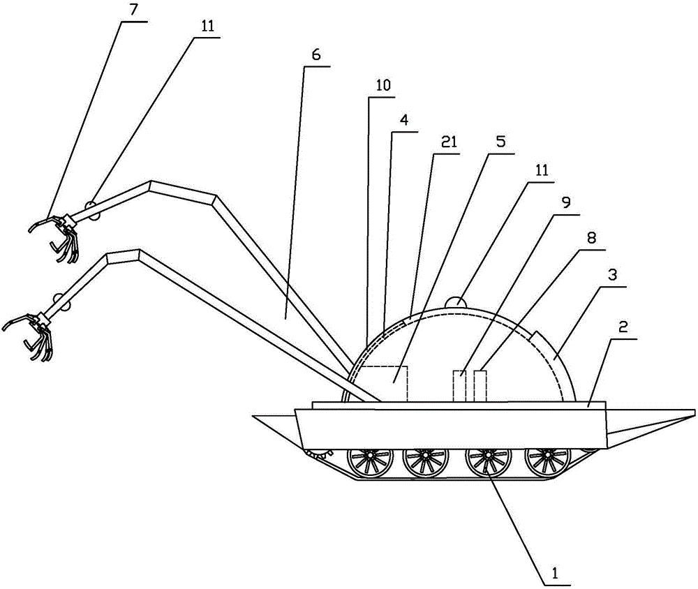
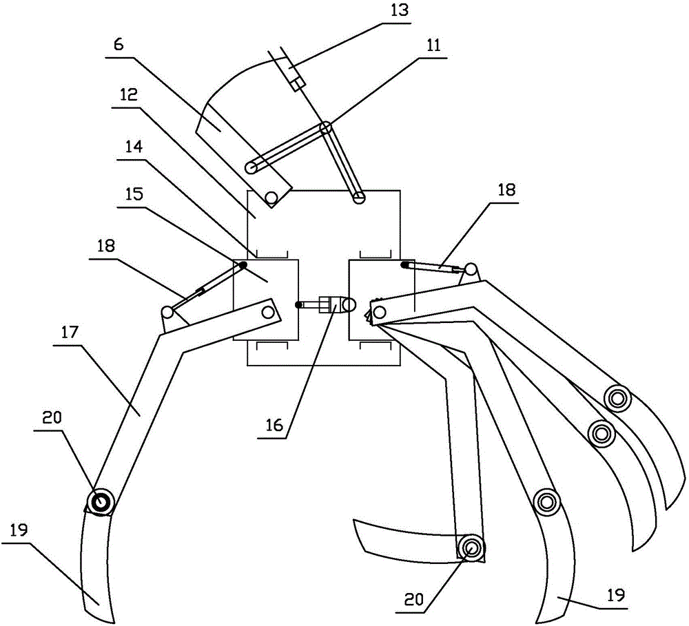
[0021] Such as Figure 1-2 As shown, a special intelligent engineering rescue and disaster relief vehicle includes a traveling mechanism 1 and a power mechanism. A rotating platform 2 is arranged on the top of the traveling mechanism 1, and a control protection compartment 21 is arranged on the rotation platform 2. The rear side of the control protection compartment 21 is provided with There is a door 3, a transparent window 4 is provided on the front side, a control panel 5 connected with the power mechanism is arranged in the operation protection compartment, and a number of mechanical arms connected with the control panel are arranged on the rotating platform 2 outside the control protection compartment 21 6. A manipulator 7 is provided at the front en...


PUM


Abstract

A special intelligent engineering emergency rescue and disaster relief vehicle comprises a traveling mechanism and a power mechanism. A rotary table is arranged at the top of the traveling mechanism. A control protective cabin is arranged on the rotary table. A cabin door is arranged on the rear side of the control protective cabin. A transparent window is arranged on the front side of the control protective cabin. A console connected with a power mechanism is arranged in the control protective cabin. A plurality of mechanical arms connected with the console are arranged on the portion, outside the control protective cabin, of the rotary table. A manipulator is arranged at the front end of each mechanical arm. The mechanical arms, the manipulators and the rotary table are connected with the console. The special intelligent engineering emergency rescue and disaster relief vehicle is reasonable in structural design, broad in application range and high in intelligence degree, a rescuer is fully protected, various operation tasks can be completed during engineering construction, and the problems in the prior art are solved.

Description

Technical field: [0001] The invention relates to a special intelligent engineering emergency rescue vehicle. Background technique: [0002] With the development of society and economy, the concept of emergency rescue in our country is constantly being innovated. The main task of emergency rescue is to quickly deal with danger, search for survivors and deal with various possible dangers. Search and rescue work should be carried out immediately after the danger occurs, and correct judgment and settings must be made before the search, so that we can do as much as possible. It is possible to provide a good search and rescue environment, and dispatch appropriate engineering rescue machinery to improve rescue efficiency, but the existing equipment has its own weaknesses, basically all special equipment, and the applicable area is too narrow. Rescue requires a variety of equipment. More importantly, the existing equipment is seriously insufficient for the protection of rescuers, ...

Claims


Application Information

Patent Timeline
Patent Type & Authority Applications(China)
IPC IPC(8): B25J5/00B25J15/02E02F3/358
CPCB25J5/007B25J15/0009B25J15/02E02F3/358
Inventor 李建纯鲁伟忠刘志
Owner 鲁伟忠
Why Eureka
Try Eureka