Rotor core of brushless motor

A technology of rotor iron core and brushless motor, which is applied in the manufacture of motor generators, stator/rotor bodies, electric components, etc., which can solve the problem of affecting the heat dissipation and working performance of fans, low effective utilization of permanent magnets, and built-in rotors. Problems such as large magnetic flux leakage of punching sheets, to achieve excellent magnetic isolation effect, reduce magnetic flux leakage phenomenon, and weaken the effect of local magnetic flux leakage

Pending Publication Date: 2016-08-17
浙江希尔富电气股份有限公司
View PDF0 Cites 7 Cited by
  • Summary
  • Abstract
  • Description
  • Claims
  • Application Information

AI Technical Summary

Problems solved by technology

The built-in rotor has a large magnetic flux leakage, and the effective utilization rate of the permanent magnet is low, which affects the heat dissipation and working performance of the fan

Method used


Image

  • Rotor core of brushless motor
  • Rotor core of brushless motor
  • Rotor core of brushless motor

Examples


Embodiment 1

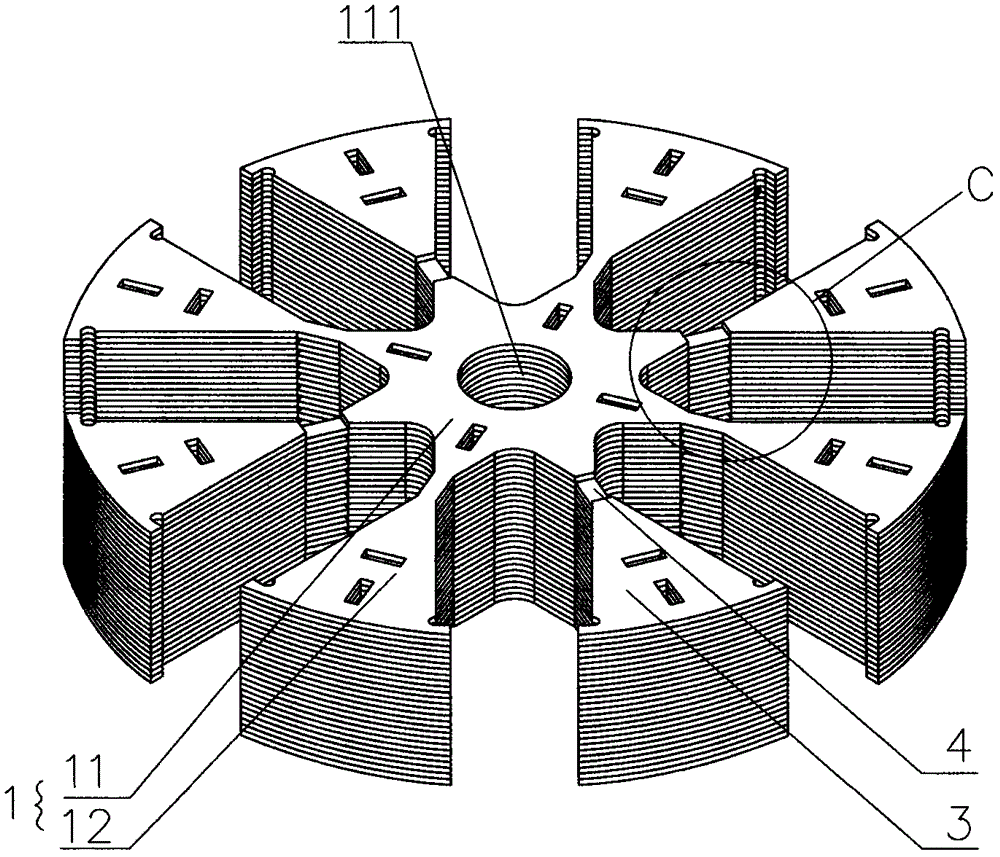
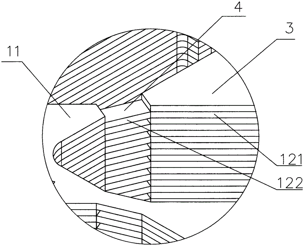
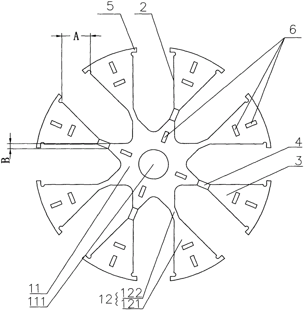
[0021] refer to figure 1 , figure 2 and image 3 , a brushless motor rotor core shown, including a core body, the core body includes a laminated rotor punch 1, the rotor punch 1 includes a main body 11, along the circumferential direction of the main body 11 uniformly spaced iron chips 12 and The block 3 located between the adjacent iron chips 12, the center of the main body 11 is provided with a shaft hole 111 for installing the rotating shaft, the block 3 is located in the middle of the adjacent iron chips 12, and the formed between the block 3 and the iron chips 12 There is a magnetic tile groove 2, which is used to install magnets, a broken bridge 4 is formed at a certain distance between the block 3 and the main body 11, and in the adjacent rotor punch 1, the lower rotor punch 1 has an upper iron chip 12 It is located directly below the piece 3 on the upper rotor punching sheet 1. The piece 3 is attached to the iron chip 12, and the magnet is interference-connected bet...

Embodiment 2

[0028] A brushless motor rotor iron core, comprising an iron core body, the iron core body includes laminated rotor punches, and the rotor punches include a main body, iron chips arranged at uniform intervals along the circumferential direction of the main body, and splices between adjacent iron chips. The center of the main body is provided with a shaft hole for installing the rotating shaft. The block is located in the middle of the adjacent iron chip. A magnetic tile groove is formed between the block and the iron chip. The magnetic tile groove is used to install the magnet, the block and the main body. Broken bridges are formed at intervals, and among the adjacent rotor punches, the iron chips on the lower rotor punch are located directly below the pieces on the upper rotor punch, and the magnets are positioned between the iron chips and the pieces. The iron core body and the connecting bridge connected between the iron core body and the main body. The difference between th...


PUM


Abstract

The invention discloses a brushless motor rotor core, which belongs to the field of motors and solves the technical problem of serious magnetic flux leakage in the brushless motor rotor in the prior art. The brushless motor rotor core provided by the invention includes a core body, an iron The core body includes laminated rotor punches. The rotor punches include a main body, iron chips arranged at intervals along the circumferential direction of the main body, and pieces located between adjacent iron chips. Magnetic tile grooves are formed between the pieces and the iron chips. A broken bridge is formed at intervals between the blocks and the main body, and among the adjacent rotor punches, the iron chips on the lower rotor punches are located directly below the pieces on the upper rotor punches.

Description

【Technical field】 [0001] The invention relates to a brushless motor rotor iron core. 【Background technique】 [0002] In recent years, permanent magnet synchronous generators for vehicles have been used more and more because of their advantages such as high efficiency, good low-speed power supply performance, low voltage adjustment rate, simple structure, reliable operation, and stable performance. There are two types of rotor punching for automotive permanent magnet generators: surface type and built-in type, and the built-in rotor punching is more widely used. The built-in rotor has a large magnetic flux leakage, and the effective utilization rate of the permanent magnet is low, which affects the heat dissipation and working performance of the fan. 【Content of invention】 [0003] The technical problem solved by the invention is to provide a rotor iron core of a brushless motor to improve the heat dissipation of the rotor. [0004] In order to solve the problems of the t...

Claims


Application Information

Patent Timeline
Patent Type & Authority Applications(China)
IPC IPC(8): H02K1/27H02K15/03
CPCH02K1/276H02K15/03
Inventor 胡君晓
Owner 浙江希尔富电气股份有限公司
Why Eureka
Try Eureka