
Fixing device for part
A technology for fixing devices and parts, applied in vise, manufacturing tools, etc., can solve the problems of uneven force, damage to the dimensional accuracy of parts, etc., to achieve the effect of uniformity and avoiding one-sided force
- Summary
- Abstract
- Description
- Claims
- Application Information
AI Technical Summary
Problems solved by technology
Method used
Image

Examples
Embodiment 1
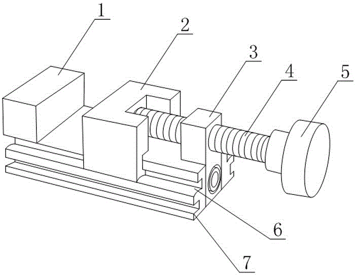
[0023] Such as figure 1 As shown, a component fixing device includes a bottom plate 7, a fixed block 1, a movable block 2 and a pushing device for pushing the movable block 2 to move toward the side of the fixed block 1. The bottom plate 7 is strip-shaped, and the The fixed block 1 is fixed on one end of the base plate 7, the pushing direction of the pushing device is along the length direction of the base plate 7, both sides of the base plate 7 are provided with chute 6 along the length direction of the base plate 7, and the movable card The block 2 is provided with two sliders that are respectively matched with different chute 6, the mating surface formed by the side of the chute 6 and the bottom surface of the slider is an arc surface, and in the depth direction of the chute 6, the The highest point of the arc surface is located between the opening end of the chute 6 and the bottom end of the chute 6; two chute 6s are provided on each side of the bottom plate 7, and the two...
Embodiment 2
[0028] The present embodiment is further limited on the basis of embodiment 1, as figure 1 As shown, as a simple implementation form of the pusher, the pusher includes a threaded rod 4, a threaded seat 3 and a handle 5, the threaded seat 3 is fixed on the bottom plate 7, and the threaded rod 4 is threaded with the threaded seat 3 , the axial direction of the threaded rod 4 is parallel to the length direction of the bottom plate 7, the turning handle 5 is fixed on the threaded rod 4, and the movable block 2 is located between the fixed block 1 and the pushing device. In the above structure, during the rotation of the threaded rod 4 , the end of the threaded rod 4 exerts a driving force on the movable block 2 , and the rotating handle 5 is used to drive the threaded rod 4 to rotate. In the above structure, the threaded seat 3 and the bottom plate 7 are detachably connected. Further, the fixed block 1 can be set in the form of a right-angle notch on it. The end face and the uppe...
PUM
 Abstract
Description
Claims
Application Information