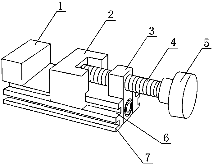
a forceps
A technology of clamp body and bottom plate, which is applied in the field of clamp body, can solve the problems of uneven force, damage to the dimensional accuracy of parts, etc., and achieve the effect of uniformity and avoiding one-sided force
- Summary
- Abstract
- Description
- Claims
- Application Information
AI Technical Summary
Problems solved by technology
Method used
Image
Examples
Embodiment 1
[0021] Such as figure 1 As shown, a kind of pliers body comprises a base plate 7, a fixed block 1, a movable block 2 and a pushing device for pushing the movable block 2 to move toward the fixed block 1, the bottom plate 7 is strip-shaped, and the fixed block 2 The clamping block 1 is fixed on one end of the base plate 7, the pushing direction of the pushing device is along the length direction of the base plate 7, and both sides of the base plate 7 are provided with chute 6 along the length direction of the base plate 7, and the movable clamping block 2 There are two sliders that are respectively matched with different chute 6; each side of the bottom plate 7 is provided with two chute 6, and the two chute 6 on the same side of the bottom plate 7 are respectively located at the upper end and the lower end of the bottom plate 7 ; The width of the upper end and the lower end of the bottom plate 7 is not equal, and both the fixed block 1 and the pushing device are connected to t...
Embodiment 2
[0025] The present embodiment is further limited on the basis of embodiment 1, as figure 1 As shown, as a simple implementation form of the pusher, the pusher includes a threaded rod 4, a threaded seat 3 and a handle 5, the threaded seat 3 is fixed on the bottom plate 7, and the threaded rod 4 is threaded with the threaded seat 3 , the axial direction of the threaded rod 4 is parallel to the length direction of the bottom plate 7, the turning handle 5 is fixed on the threaded rod 4, and the movable block 2 is located between the fixed block 1 and the pushing device. In the above structure, during the rotation of the threaded rod 4 , the end of the threaded rod 4 exerts a driving force on the movable block 2 , and the rotating handle 5 is used to drive the threaded rod 4 to rotate. In the above structure, the threaded seat 3 and the bottom plate 7 are detachably connected. Further, the fixed block 1 can be set in the form of a right-angle notch on it, and the two surfaces of th...
PUM
 Abstract
Description
Claims
Application Information
 - R&D
- Intellectual Property
- Life Sciences
- Materials
- Tech Scout
- Unparalleled Data Quality
- Higher Quality Content
- 60% Fewer Hallucinations
Browse by: Latest US Patents, China's latest patents, Technical Efficacy Thesaurus, Application Domain, Technology Topic, Popular Technical Reports.
© 2025 PatSnap. All rights reserved.Legal|Privacy policy|Modern Slavery Act Transparency Statement|Sitemap|About US| Contact US: help@patsnap.com

