Eureka AIR delivers breakthrough ideas for toughest innovation challenges, trusted by R&D personnel around the world.

a dimming circuit

A dimming circuit and circuit technology, applied to light sources, electric light sources, electrical components, etc., can solve the problems of inaccurate dimming detection, deviation, inconsistent dimming status, etc., achieve high dimming consistency and avoid misjudgment Effect

Active Publication Date: 2018-06-19
SHAANXI REACTOR MICROELECTRONICS
View PDF9 Cites 2 Cited by
  • Summary
  • Abstract
  • Description
  • Claims
  • Application Information

AI Technical Summary

Problems solved by technology

[0003] On the one hand, the falling time of the capacitor voltage is greatly affected by the parameters of the capacitor, such as the actual capacity of the capacitor, the leakage current of the capacitor, the temperature characteristics of the capacitor, and these parameters of capacitors from different manufacturers cannot be unified. There are also deviations in the parameters, which seriously affect the accuracy of switch detection; on the other hand, when the power switch is switched on and off quickly, it will cause inaccurate dimming detection, missing detection or less detection of switching actions. The result is that one switch controls multiple lights. When switching on and off the power supply quickly, there will be inconsistencies in the dimming state between the lamp and the lamp, which makes the switch dimming unable to be used in commercial large-area areas such as shopping malls and supermarkets.

Method used


Image

  • a dimming circuit
  • a dimming circuit
  • a dimming circuit

Examples


Embodiment Construction

[0043] Below in conjunction with accompanying drawing, further elaborate the present invention. It should be understood that these examples are only used to illustrate the present invention and are not intended to limit the scope of the present invention. In addition, it should be understood that after reading the content taught by the present invention, those skilled in the art may make various changes or modifications to the present invention, and these equivalent forms also fall within the scope defined by the appended claims of the present application.

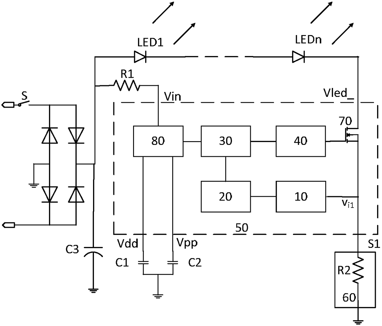
[0044] As attached to the manual figure 1 As shown, it contains an LED light string, and the dimming circuit includes a current detection module 10, a judgment module 20, a switching module 30, a driving module 40, a sampling circuit 60, an LED light string, a power tube 70, and a power supply module 80; at least one power The input end of the tube is connected to the negative pole of the LED light string; the output end ...


PUM


Abstract

The invention discloses a dimming circuit, comprising a rectification circuit, an LED lamp string, a current detection module, a judgment module, a switching module, a driving module, a sampling circuit, at least one power tube and a power supply module, the input end of the power tube is connected to an external LED The negative electrode of the light string and the output end of the power tube are connected to the current detection module and the sampling circuit. The invention avoids the influence of the capacitance in the circuit on the detection accuracy of the switch by detecting the duration of whether the current flows through the source of the power tube. The problem of inconsistency in discharge time caused by differences in external application devices and misjudgment of switch on-off is avoided. The internal clock timer of the chip controls the preset time, and the dimming consistency is high, which avoids the misjudgment of the detection by the switch interference, and ensures that the switch dimming method can be used in a large area.

Description

technical field [0001] The invention relates to the technical field of LED lighting control, in particular to an LED switch dimming circuit. Background technique [0002] There are many forms of LED dimming circuits currently on the market, mainly including thyristor dimming, PWM dimming and switch dimming. Most switch dimming is performed by detecting the on-off action of the power switch. This working method is based on threshold value comparison. Change, when the voltage on the capacitor is higher than the first threshold, it is judged that the switch is off, when the voltage on the capacitor is lower than the second threshold, the switch is on, the on-off action of the power switch is judged, and the on-off action is counted , The counting result is maintained after power failure, and a corresponding reference voltage is output according to the number of power failures to control the current flowing through the LED, thereby realizing dimming. This dimming method has th...

Claims


Application Information

Patent Timeline
Patent Type & Authority Patents(China)
IPC IPC(8): H05B33/08H05B44/00
CPCH05B45/14
Inventor 杨世红王虎
Owner SHAANXI REACTOR MICROELECTRONICS
Why Eureka
Eureka Blog
Learn More