Eureka AIR delivers breakthrough ideas for toughest innovation challenges, trusted by R&D personnel around the world.

Method, system and apparatus for detecting optical fiber fault in passive optical network

An optical fiber fault detection and passive optical network technology, which is applied in the field of passive optical networks, can solve the problems of misjudging normal optical fibers as faulty optical fibers, unable to achieve accurate detection, and low accuracy of optical fiber fault detection schemes, so as to avoid optical fiber faults. Misjudgment, low cost, and low complexity

Active Publication Date: 2011-04-06
NEW H3C TECH CO LTD
View PDF0 Cites 0 Cited by
  • Summary
  • Abstract
  • Description
  • Claims
  • Application Information

AI Technical Summary

Problems solved by technology

[0005] However, for the first detection method, if the optical fiber is normal, but the ONU has no upstream traffic for a certain period of time, that is, the ONU has no upstream light, it is easy to misjudge the normal optical fiber as a faulty optical fiber; for the second detection If there is no new ONU sending a registration request to the OLT within the discovery window, it is easy to misjudge a normal fiber as a faulty fiber
It can be seen that the accuracy of the existing optical fiber fault detection scheme is low, and it is impossible to achieve accurate detection

Method used


Image

  • Method, system and apparatus for detecting optical fiber fault in passive optical network
  • Method, system and apparatus for detecting optical fiber fault in passive optical network
  • Method, system and apparatus for detecting optical fiber fault in passive optical network

Examples


Embodiment Construction

[0034] In order to make the object, technical solution and advantages of the present invention clearer, the present invention will be further described in detail below with reference to the accompanying drawings and examples.

[0035] In order to solve the problems in the prior art, the present invention first proposes a ring network-based optical fiber protection system, and then provides a brand-new optical fiber fault detection scheme based on the optical fiber protection system.

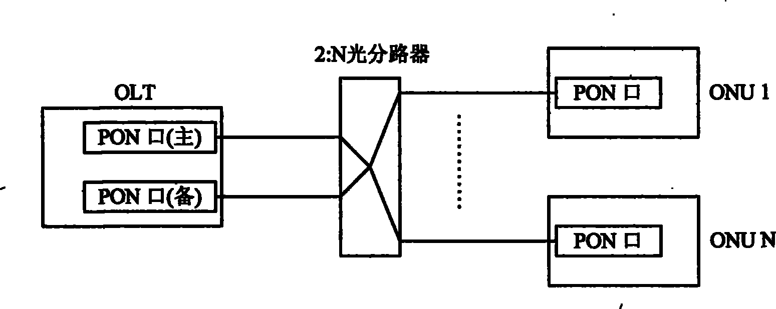
[0036] The structure of the optical fiber protection system based on the ring network provided by the present invention can be found in image 3As shown, it includes: OLT, ONU, and distribution box. The two optical fibers output by the OLT are connected in series to all the distribution boxes. The output of the distribution box is an optical fiber connected to the ONU. The two optical fibers output by the OLT start from the optical module of the OLT. Then terminate at the GE optical port of the O...


PUM


Abstract

The invention provides an optical fiber fault detection method in PON. The method comprises: outputting two optical fibers from optical line terminal (OLT) to separately couple all junction boxed, and outputting one optical fiber from the junction boxes to connect an optical network unit (ONU), wherein, the two optical fibers outputted by OLT separately start from a first optical module and a second optical module of OLT, and pass through each junction box to separately return to a first GE optical port and a second GE optical port of OLT; the first GE optical port and the second GE optical port separately detect if light is on the optical fiber connected with the first GE optical port and the second GE optical port, and report detection result to CPU, then CPU determines if the two optical fibers outputted by OLT turn up fault according to the received detection result. Moreover, the invention also provides an optical fiber protection system in PON, a junction box and an OLT. Making use of the technical scheme provided by the invention can improve accuracy of optical fiber fault detection.

Description

technical field [0001] The present invention relates to a passive optical network (PON, Passive Optical Network) technology, in particular to an optical fiber fault detection system and device in a passive optical network. Background technique [0002] PON is a passive optical network with a point-to-multipoint structure. It has the advantages of easy maintenance, high bandwidth, and low cost. It is currently a widely used optical access technology. figure 1 It shows a schematic diagram of the PON structure, mainly including: Optical Line Terminal (OLT, Optical Line Terminal), Passive Optical Splitter (POS, Passive Optical Splitter) and Optical Network Unit (ONU, Optical Network Unit), between OLT, POS and ONU Connected via optical fiber. [0003] Such as figure 1 As shown, PON has the characteristics of single-fiber transmission of bidirectional data and point-to-multipoint. In this case, if the main fiber between OLT and POS fails, it will inevitably cause a large number...

Claims


Application Information

Patent Timeline
Patent Type & Authority Patents(China)
IPC IPC(8): H04Q11/00H04B10/08H04B10/03H04B10/075
Inventor 孙强冯武通马国强冯剑
Owner NEW H3C TECH CO LTD
Why Eureka
Eureka Blog
Learn More