High-pressure water cleaning vehicle provided with rotary water spray supports

A technology for high-pressure cleaning vehicles and water spray racks, applied in road cleaning, cleaning methods, construction, etc., can solve the problems of single structure of water spray racks, inability to clean in place, and limited cleaning efficiency. Good cleaning effect and large cleaning range

Active Publication Date: 2016-11-23
WUHAN UNIV OF TECH
View PDF7 Cites 13 Cited by
  • Summary
  • Abstract
  • Description
  • Claims
  • Application Information

AI Technical Summary

Problems solved by technology

[0004] At present, there are two main types of cleaning vehicles used in tunnel inner walls and highway noise screens. One is the rolling brush cleaning vehicle. The traditional single rolling brush cleaning method has low efficiency and the cleaning liquid will also cause certain pollution to the environment. ,Multi-rolling brush cleaning vehicles are more expensive, consume more energy, and have higher maintenance costs. The cost performance is low, and the inner walls of narrow grooves cannot be cleaned in place; Cleaning, high-pressure water cleaning is an emerging cleaning method. Because it uses high-pressure water jet technology, the water consumption per hour is low, clean and environmentally friendly, and the cleaning efficiency is high. It has developed rapidly in recent years and has a broad application prospect.
However, there are few domestic multi-functional cleaning vehicles. The existing cleaning vehicles have a single spray frame structure, and the width of one cleaning is relatively limited. The cleaning efficiency is limited by the curvature of the wall.

Method used


Image

  • High-pressure water cleaning vehicle provided with rotary water spray supports
  • High-pressure water cleaning vehicle provided with rotary water spray supports
  • High-pressure water cleaning vehicle provided with rotary water spray supports

Examples


Embodiment Construction

[0028] In order to better understand the present invention, the present invention will be further described below in conjunction with the accompanying drawings and specific embodiments.

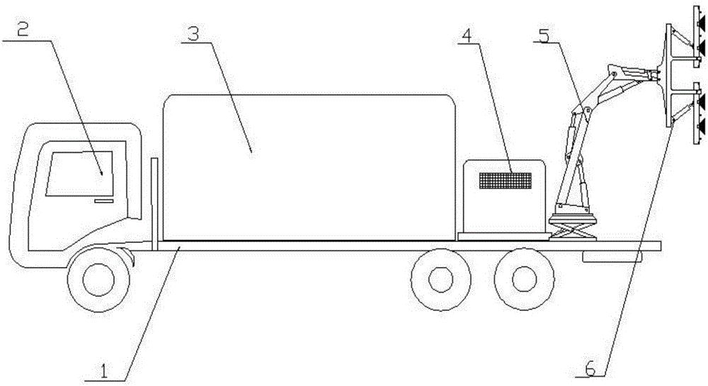
[0029] Such as figure 1 The high-pressure cleaning vehicle with a rotary spray rack includes a driver's cab 2 and a chassis 1. A water storage tank 3, a power and control unit 4 and a position adjustment unit 5 are sequentially installed on the chassis 1. The position adjustment unit 5 is free The end is connected with a cleaning device 6, and the cleaning device 6 communicates with the water storage tank 3 through a water pipe; wherein, the power and control unit 4 is electrically connected with the position adjustment unit 5 and the cleaning device 6 respectively, and controls the work of the position adjustment unit 5 and the cleaning device 6. .

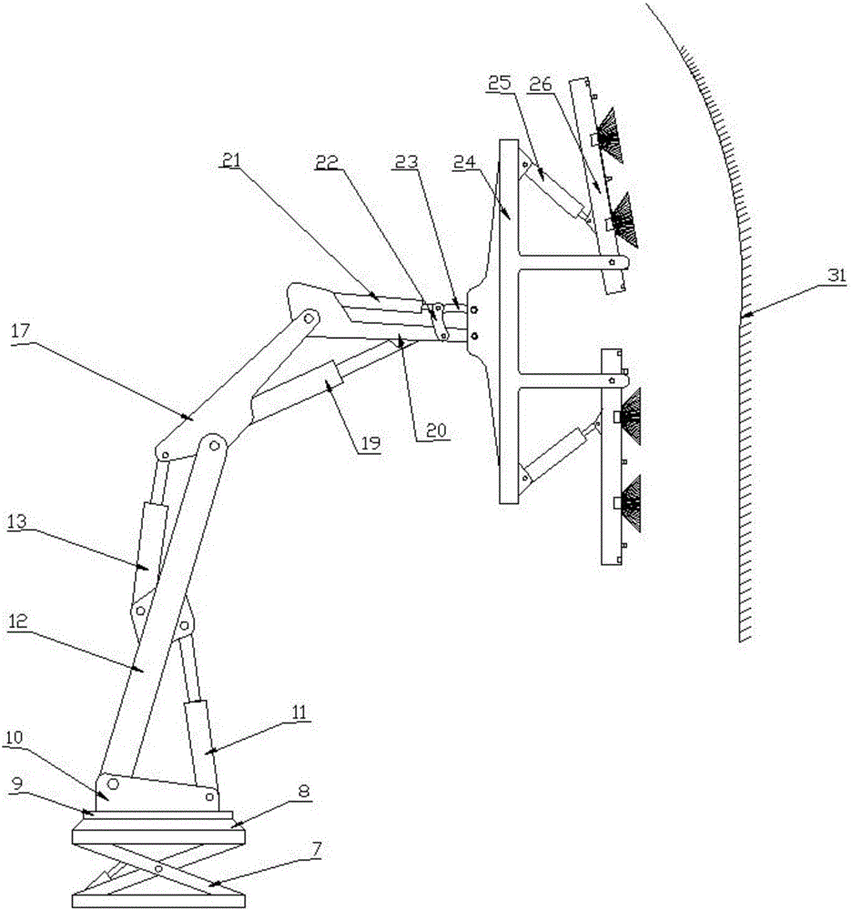
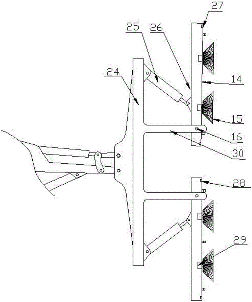
[0030] Such as figure 2 As shown, the cleaning device 6 includes a main support 24, a secondary support 30, a water spray frame 26 and a hyd...


PUM


Abstract

The invention discloses a high-pressure water cleaning vehicle provided with rotary water spray supports. The high-pressure water cleaning vehicle comprises a driving cab and a chassis, wherein a water tank, a power and control unit and a position adjusting unit are sequentially mounted on the chassis, the free end of the position adjusting unit is connected with a cleaning device, and the cleaning device communicates with the water tank through a water pipe; the power and control unit is electrically connected with the position adjusting unit and the cleaning device; the cleaning device comprises a main bracket, auxiliary brackets, the water spray supports and hydraulic cylinders I, one side of the main bracket is connected with the position adjusting unit, the other side of the main bracket extends outwards to form the two auxiliary brackets, and the free end of each auxiliary bracket is hinged with one end of the corresponding water spray support; the hydraulic cylinders I are hinged with the main bracket, and rod ends of the hydraulic cylinders I are hinged with the water spray supports; a plurality of spray nozzles are distributed on the outer side of the water spray supports in a length direction at intervals. The high-pressure water cleaning vehicle provided with the rotary water spray supports has the beneficial effects as follows: the water spray supports are designed into a rotary type, positions and angles of the water spray supports are flexible and variable, so that the water spray supports are not only suitable for cleaning a plane, but also is suitable for cleaning a wall surface with curvature change, and dual-surface cleaning is also realized.

Description

technical field [0001] The invention relates to a cleaning device, in particular to a high-pressure cleaning vehicle with a rotary water spray frame. Background technique [0002] With the rapid development of highway construction and urban road traffic construction, the laying of highway tunnels and urban viaducts is also very rapid. Due to the increase in the number of cars, the pollution of the tunnel is becoming more and more serious due to the harmful gases emitted by the vehicles and the dust raised, and the noise generated is also increasing. [0003] For some long tunnels, the ventilation is poor, and the dust is easy to stick to the tunnel wall; the carbon black in the vehicle exhaust and the dust in the dust are mixed together, and finally deposited on the surface of the inner wall of the tunnel, forming obvious stains over time. , The lighting equipment in the tunnel will also suffer from it, which will bring great safety hazards to the tunnel traffic. These sta...

Claims


Application Information

Patent Timeline
Patent Type & Authority Applications(China)
IPC IPC(8): E01H1/00
CPCE01H1/005
Inventor 苏楚奇付强邓亚东夏冰何佩芸雷星星舒绍文邓刚林管灵
Owner WUHAN UNIV OF TECH
Why Eureka
Try Eureka