a conveying mechanism

A technology of conveying mechanism and conveying board, which is applied in the direction of conveyor, conveyor objects, transportation and packaging, etc., and can solve the problem of inaccurate parking and other problems

Active Publication Date: 2018-12-04
BOZHON PRECISION IND TECH CO LTD
View PDF5 Cites 0 Cited by
  • Summary
  • Abstract
  • Description
  • Claims
  • Application Information

AI Technical Summary

Problems solved by technology

[0002] Conveyor mechanisms, especially wire-transmission conveyor mechanisms, are widely used in automated assembly production lines, but the conveyor mechanisms used at this stage need to be transported or parked in response to the power source drive beat of the conveyor mechanism in the conveyor project, and the material parking position is determined by The power source drive beat control of the conveying mechanism cannot stop accurately

Method used


Image

  • a conveying mechanism
  • a conveying mechanism
  • a conveying mechanism

Examples


Embodiment Construction

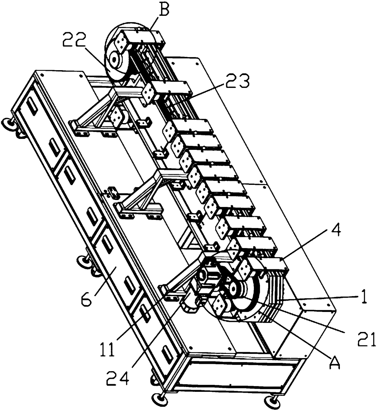
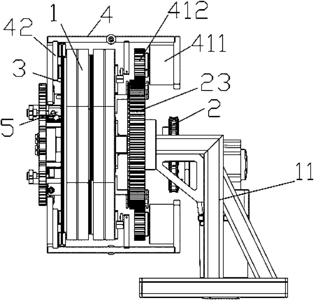
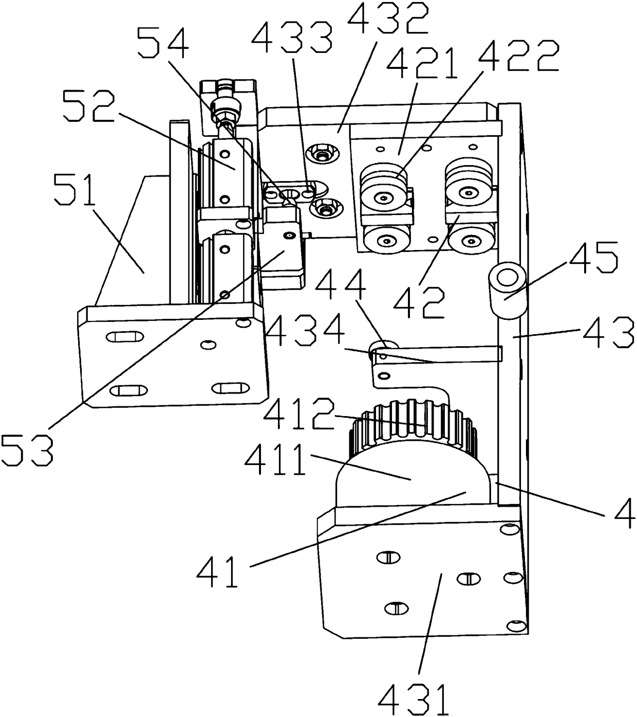
[0038] see Figure 1 to Figure 5 , a conveying mechanism, including a conveying board 1, a drive transmission assembly 2 arranged on one side of the conveying board 1, a running track 3 correspondingly arranged on the other side of the conveying board 1 and matched with the drive transmission assembly 2, and arranged on One end on the conveying plate 1 is provided with a material trolley 4 with a clutch drive wheel assembly 41 driven by the drive transmission assembly 2, and the other end of the material trolley 4 is provided with a running wheel assembly 42 corresponding to and used in conjunction with the running track 3;

[0039] The clutch drive wheel assembly 41 includes a clutch 411 arranged on the material trolley 4, and a trolley drive wheel 412 connected to the clutch 411 and used in conjunction with the drive transmission assembly 2, and the conveying plate 1 is also provided with the material trolley 4 and The clutch 411 arranged on it cooperates with the gear stop ...


PUM


Abstract

The invention provides a conveying mechanism. The conveying mechanism comprises a conveying plate, a driving transmission assembly, an operating orbit and a material trolley, wherein the driving transmission assembly is arranged on one side of the conveying plate; the operating orbit is correspondingly arranged on the other side of the conveying plate and matched with the driving transmission assembly; and the material trolley is arranged at one end of the conveying plate and provided with a clutch driving wheel assembly driven by the driving transmission assembly, and the other end of the material trolley is provided with an operating wheel assembly which corresponds to and is matched with the operating orbit. The clutch driving wheel assembly comprises a clutch arranged on the material trolley and a trolley driving wheel which is connected to the clutch and matched with the driving transmission assembly, and the conveying plate is further provided with a stop-blocking assembly which is matched with the material trolley and the clutch arranged on the material trolley. According to the conveying mechanism, material stopping positions are not affected by driving power source driving beats.

Description

technical field [0001] The invention relates to the field of automation equipment, in particular to a conveying mechanism. Background technique [0002] Conveyor mechanisms, especially wire-transmission conveyor mechanisms, are widely used in automated assembly production lines. However, the conveyor mechanisms used at this stage need to be transported or parked in response to the power source drive beat of the conveyor mechanism. The material parking position is determined by The power source driving beat control of the conveying mechanism cannot stop accurately. [0003] Therefore, it is necessary to provide a conveying mechanism to solve the above problems. Contents of the invention [0004] The object of the present invention is to provide a conveying mechanism in which the stopping position of materials is not affected by the driving cycle of the driving power source. [0005] The present invention realizes above-mentioned purpose through following technical scheme:...

Claims


Application Information

Patent Timeline
Patent Type & Authority Patents(China)
IPC IPC(8): B65G23/26B65G47/88
CPCB65G23/26B65G47/88
Inventor 吕绍林杨愉强吴小平周剑飞
Owner BOZHON PRECISION IND TECH CO LTD
Why Eureka
Try Eureka