Unmanned aerial vehicle

A technology of drones and airframes, applied in the field of aircraft, can solve problems such as high cost and poor noise reduction effect, and achieve the effect of cost saving

Inactive Publication Date: 2017-01-04
SHANGHAI YUDE COMM TECH
View PDF4 Cites 8 Cited by
  • Summary
  • Abstract
  • Description
  • Claims
  • Application Information

AI Technical Summary

Problems solved by technology

[0004] The disadvantages of the prior art are that the cost is high and the noise reduction effect is poor

Method used


Image

  • Unmanned aerial vehicle
  • Unmanned aerial vehicle

Examples


Embodiment 1

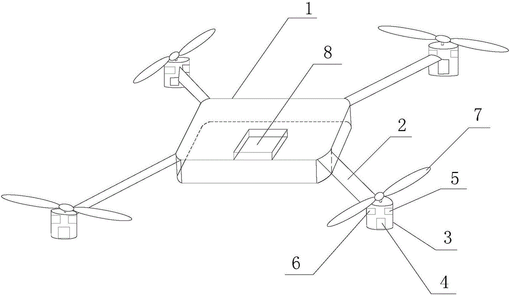
[0015] figure 1 It is a schematic structural diagram of a UAV provided in Embodiment 1 of the present invention. The UAV in this embodiment may be a multi-rotor UAV, such as a quad-rotor UAV, an octo-rotor UAV, and the like. refer to figure 1 , taking the quadrotor drone as an example, the drone provided in this embodiment specifically includes: a fuselage 1, the fuselage 1 is provided with at least one connecting arm 2 extending outward, each of the connecting arms 2 A housing 3 is provided on one end of the outer extension, and a first motor 4 , a noise collecting device 5 and an acoustic wave output device 6 are integrated in the housing 3 , and a first rotor connected to the first motor 4 is provided on the upper part of the housing 3 7. A control module 8 is integrated in the fuselage 1; the noise collection device 5 is used to collect the noise generated during the flight of the drone and send it to the control module 8; the control module 8 is used to control the The ...

Embodiment 2

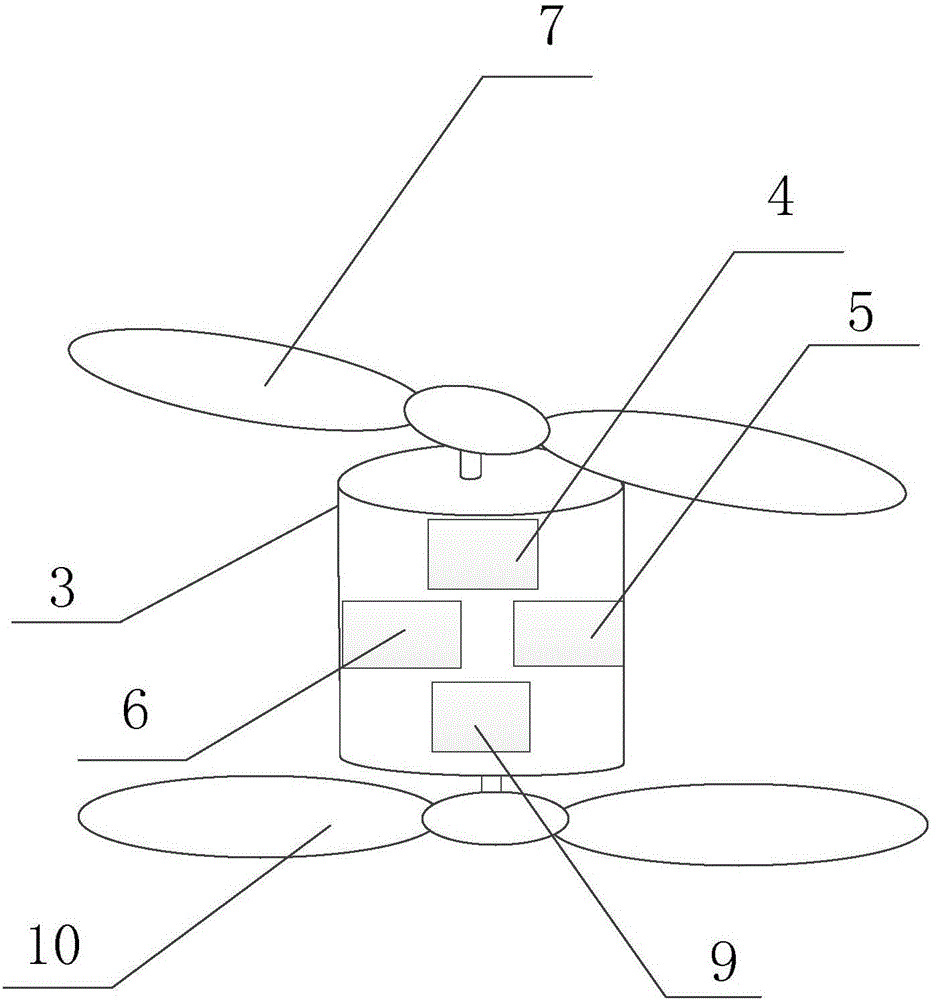
[0026] figure 2 A schematic structural diagram of an unmanned aerial vehicle provided in Embodiment 2 of the present invention, specifically a structural schematic diagram at the housing 3. In this embodiment, on the basis of the above-mentioned embodiments, it is preferred that the housing 3 is also provided with a second The motor 9 is arranged below the first motor 4 , and the second rotor 10 connected to the second motor 9 is arranged on the lower part of the casing 3 .

[0027] Wherein, the bottom of casing 3 is provided with output hole, and the bottom of second motor 9 is provided with output shaft, and output shaft passes through the output hole of casing 3 bottom and is connected with second rotor 10, drives output shaft when second motor 9 works Rotate, and then drive the second rotor 10 to rotate.

[0028] Preferably, the noise collecting device 5 and the acoustic wave output device 6 in each of the housings 3 are arranged on the inner wall of the housing 3, and a...

Embodiment 3

[0034] In this embodiment, on the basis of Embodiment 1, it is preferable to further increase the control module 8 to be further used to control any pair of drones located on the diagonal when the UAV receives the control command of vertical ascent / vertical descent. Two first motors 4 are in working state, and other first motors 4 are turned off.

[0035] Among them, when the UAV is vertically ascending or descending, the rotor only needs to provide the buoyancy in the vertical direction, and does not need to provide the horizontal component. The two first motors 4 on the top are in working condition, while the other first motors 4 are turned off.

[0036] On the basis of the above technical solution, preferably, the control of any pair of two first motors 4 located on the diagonal to be in the working state specifically includes: controlling any pair of the two first motors 4 located on the diagonal 4 are started sequentially with a preset time difference, so that the noises...


PUM


Abstract

The embodiment of the invention discloses an unmanned aerial vehicle which comprises a body, a noise collecting device and a control module, wherein the body is provided with at least one connecting arm extending outwards, a shell is arranged on one end, extending outwards, of each connecting arm, a first motor, the noise collecting device and an acoustic wave output device are integrated in the shell, a first rotor wing connected with the first motor is arranged at the upper part of the shell, and the control module is integrated in the body; the noise collecting device is used for collecting noise generated in flying of the unmanned aerial vehicle and sending the noise to the control module; and the control module is used for analyzing the noise, obtaining a reverse acoustic wave which is the same in frequency, same in amplitude and reverse in phase position with the noise, and sending the reverse acoustic wave via the acoustic wave output device. According to the embodiment of the invention, the noise reducing effect of the unmanned aerial vehicle can be improved, and the cost of the unmanned aerial vehicle can be saved.

Description

technical field [0001] Embodiments of the present invention relate to aircraft technology, and in particular to an unmanned aerial vehicle. Background technique [0002] With the continuous advancement of drone technology, drones have been widely used in the daily life of users, such as using drones for aerial photography and delivery. However, the drone will make a lot of noise when it is working, which will make the person being photographed or the user feel uncomfortable. [0003] The noise reduction technology of the existing UAV is mainly by improving the material of the UAV engine cover (such as nanofiber acoustic damping material), so that the noise propagates upwards, thereby reducing the noise pollution under the UAV. [0004] The disadvantages of the prior art are high cost and poor noise reduction effect. Contents of the invention [0005] An embodiment of the present invention provides an unmanned aerial vehicle, so as to reduce the cost of the unmanned aeria...

Claims


Application Information

Patent Timeline
Patent Type & Authority Applications(China)
IPC IPC(8): B64C1/40
CPCB64C1/40
Inventor 周晓峰
Owner SHANGHAI YUDE COMM TECH
Why Eureka
Try Eureka