Label printing device and control method for label printing device
A printing device and labeling technology, applied in printing, typewriters, etc., can solve the problems of label paper waste, printing quality, etc.
- Summary
- Abstract
- Description
- Claims
- Application Information
AI Technical Summary
Problems solved by technology
Method used
Image

Examples
no. 1 approach
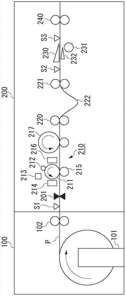
[0028] figure 1 It is a schematic diagram of the overall configuration of the label printing apparatus 200 . The paper feeding device 100 is connected to the label printing device 200 . The paper feeding device 100 has an installation unit 101 and a first transport roller 102 . A roll-shaped label paper P is rotatably set in the setting unit 101 . The label sheet P has a plurality of labels attached thereto. The roll-shaped label paper P is supplied by being rotationally driven in the direction of the arrow in the figure. The first conveying roller 102 conveys the supplied label paper P to the label printing device 200 .
[0029] The label printing device 200 has a cutting unit 201 , a printing unit 210 , a second transport roller 220 , a third transport roller 221 , a scraper (peeling unit) 230 , a pressing roller (pressing unit) 231 , a guide unit 232 , and a fourth transport roller 240 . In addition, the label printing device 200 also has a first sensor S1 , a second ...
no. 2 approach
[0083] In the first embodiment, the plurality of labels on the label sheet P are all the same size. On the other hand, in the second embodiment, a case will be described in which a plurality of labels on the label sheet P include a plurality of types of labels different in size from each other. In addition, the configurations of the paper feeding device 100 and the label printing device 200 in the second embodiment are the same as the configurations of the paper feeding device 100 and the label printing device 200 in the first embodiment, and thus description thereof will be omitted.
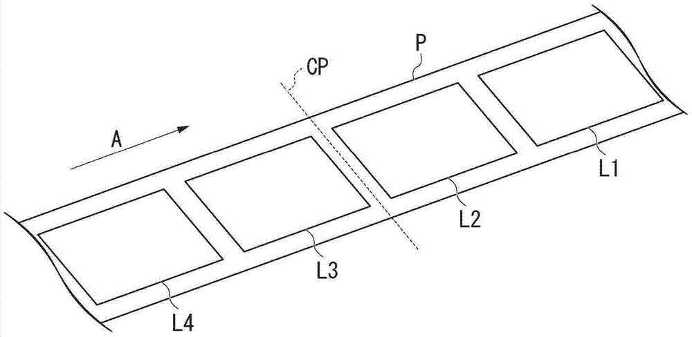
[0084] Figure 15 It is a schematic diagram of the cutting position of the label paper P in the second embodiment. Such as Figure 15 As shown, labels L1 to L4 are pasted on the label paper P. Label L1 and label L3 are small labels, and label L2 and label L4 are large labels.
[0085] Then, the cutting unit 201 cuts the first label paper P1 at the cutting position CP between the large label ...
no. 3 approach
[0090] In the first embodiment and the second embodiment, the cutting unit 201 cuts the label paper P and separates it into the first label paper P1 and the second label paper P2. On the other hand, in the third embodiment, a case where the roll label paper set in the setting unit 101 runs out will be described. In addition, the configurations of the paper feeding device 100 and the label printing device 200 in the third embodiment are the same as the configurations of the paper feeding device 100 and the label printing device 200 in the first embodiment, and thus description thereof will be omitted.
[0091] Figure 17 It is a schematic diagram of the label printing apparatus 200 in the state where the first label paper P1 is used up in the third embodiment. Such as Figure 17 As shown, after the first label paper P1 set in the setting part 101 is used up, the rear end of the first label paper P1 passes through the printing part 210 . Therefore, it is necessary to connect ...
PUM
 Abstract
Description
Claims
Application Information
 - R&D
- Intellectual Property
- Life Sciences
- Materials
- Tech Scout
- Unparalleled Data Quality
- Higher Quality Content
- 60% Fewer Hallucinations
Browse by: Latest US Patents, China's latest patents, Technical Efficacy Thesaurus, Application Domain, Technology Topic, Popular Technical Reports.
© 2025 PatSnap. All rights reserved.Legal|Privacy policy|Modern Slavery Act Transparency Statement|Sitemap|About US| Contact US: help@patsnap.com