Unlock instant, AI-driven research and patent intelligence for your innovation.
Conductive ink quick stirring device for RFID tag antenna manufacturing
What is Al technical title?
Al technical title is built by PatSnap Al team. It summarizes the technical point description of the patent document.
A technology of RFID tags and conductive inks, applied in the direction of mixer accessories, transportation and packaging, dissolution, etc., can solve problems such as complex structure, uneven mixing, slow stirring speed, etc., achieve protection devices, reduce impact force, and increase stability Effect
Inactive Publication Date: 2017-02-01
JIANGSU WENRUI INTELLIGENT TECH CO LTD
View PDF6 Cites 2 Cited by
Summary
Abstract
Description
Claims
Application Information
AI Technical Summary
This helps you quickly interpret patents by identifying the three key elements:
Problems solved by technology
Method used
Benefits of technology
Problems solved by technology
[0006] In order to overcome the disadvantages of complex structure, slow stirring speed and uneven stirring in the current conductive ink stirring device, the technical problem to be solved by the present invention is to provide a RFID tag antenna with simple structure, fast stirring speed and uniform stirring. Conductive ink fast stirring device
Method used
Image
Click on the blue label to locate the original text in one second.
Reading with bidirectional positioning of images and text.
Examples
Embodiment 1
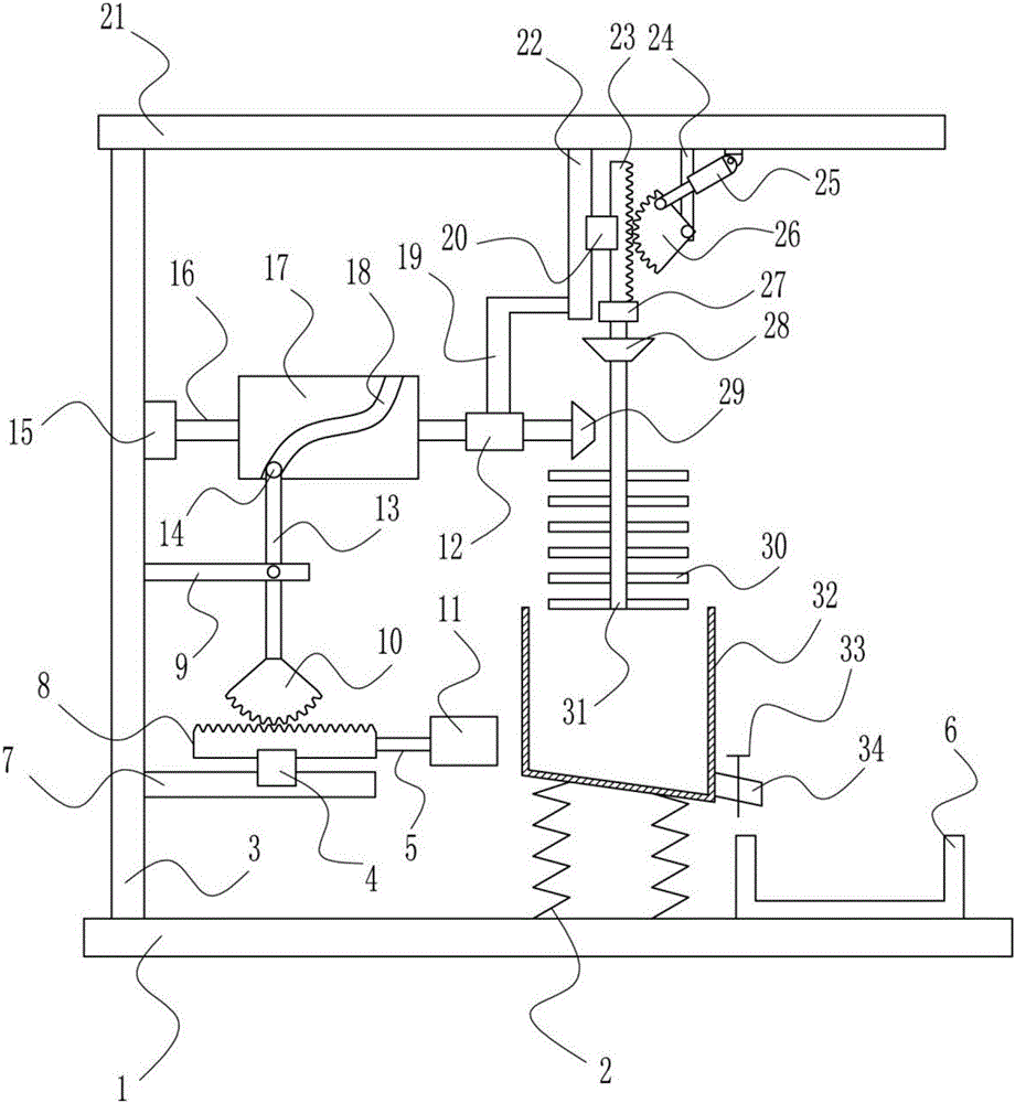
[0039] A kind of rapid stirring device for conducting ink for making RFID tag antenna, such as figure 1 As shown, it includes bottom plate 1, elastic member 2, left frame 3, first slider 4, connecting rod 5, collection frame 6, first slide rail 7, first rack 8, fixed rod 9, first sector gear 10. Top block 11, first bearing seat 12, swing lever 13, block 14, second bearing seat 15, first rotating shaft 16, cylindrical cam 17, bracket 19, second slider 20, top plate 21, second Slide rail 22, second rack 23, pole 24, electric push rod 25, second sector gear 26, motor 27, first bevel gear 28, second bevel gear 29, stirring rod 30, second rotating shaft 31, stirring Frame 32, electric control valve 33 and discharge port 34, elastic member 2 is arranged symmetrically on the top right side of bottom plate 1, collecting frame 6 is arranged on the right side of bottom plate 1 top, collecting frame 6 is located on the right side of elastic member 2, and the top left side of bottom plate...
Embodiment 2
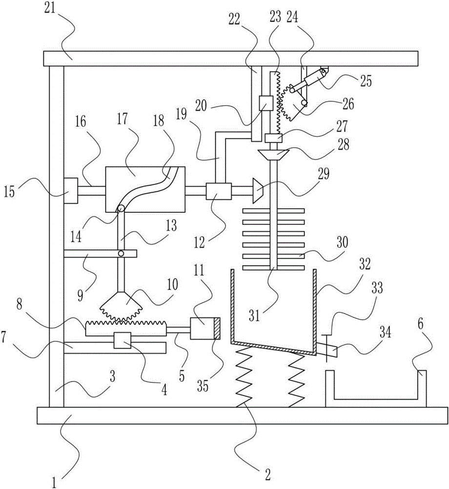
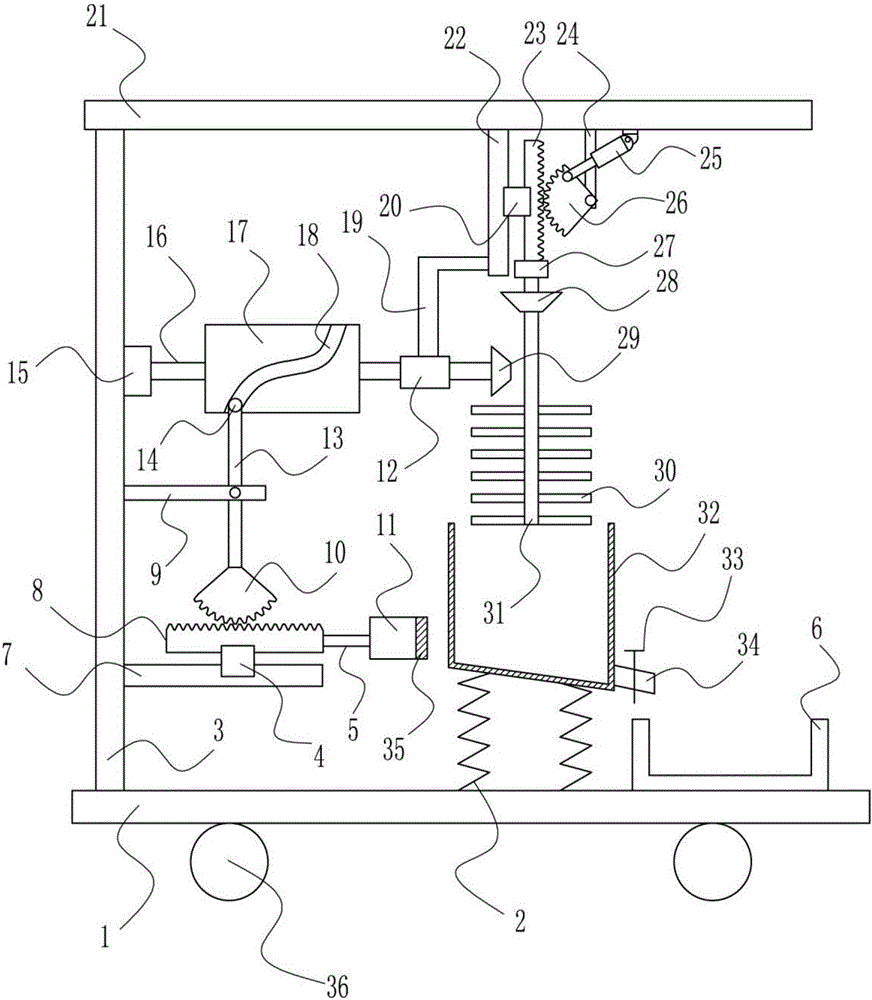
[0041] A kind of rapid stirring device for conducting ink for making RFID tag antenna, such as Figure 1-8 As shown, it includes bottom plate 1, elastic member 2, left frame 3, first slider 4, connecting rod 5, collection frame 6, first slide rail 7, first rack 8, fixed rod 9, first sector gear 10. Top block 11, first bearing seat 12, swing lever 13, block 14, second bearing seat 15, first rotating shaft 16, cylindrical cam 17, bracket 19, second slider 20, top plate 21, second Slide rail 22, second rack 23, pole 24, electric push rod 25, second sector gear 26, motor 27, first bevel gear 28, second bevel gear 29, stirring rod 30, second rotating shaft 31, stirring Frame 32, electric control valve 33 and discharge port 34, elastic member 2 is arranged symmetrically on the top right side of bottom plate 1, collecting frame 6 is arranged on the right side of bottom plate 1 top, collecting frame 6 is located on the right side of elastic member 2, and the top left side of bottom pl...
PUM
Abstract
The invention relates to a stirring device, particularly a conductive ink quick stirring device for RFID tag antenna manufacturing. The invention aims to provide a conductive ink quick stirring device for RFID tag antenna manufacturing, which has the advantages of simple structure, high stirring rate and uniform stirring. In order to solve the technical problems, the invention provides a conductive ink quick stirring device for RFID tag antenna manufacturing. The conductive ink quick stirring device for RFID tag antenna manufacturing comprises a bottom plate, elastic parts, a left rack, a first slider, a connecting rod, a collecting frame, a first slide rail, a first rack, a fixed link, a first quadrant gear, a jacking block and the like, wherein the right side of the top of the bottom plate is symmetrically provided with the elastic part; the right side of the top of the bottom plate is provided with the collecting frame; and the collecting frame is positioned on the right side of the elastic parts. The conductive ink quick stirring device achieves the effects of simple structure, high stirring rate and uniform stirring. The working personnel can implement quick stirring on the conductive ink by controlling the device, thereby enhancing the work efficiency.
Description
technical field [0001] The invention relates to a stirring device, in particular to a rapid stirring device for conductive ink used for making RFID tag antennas. Background technique [0002] The RFID tag antenna is the transponder antenna of the RFID electronic tag, and it is a communication induction antenna. Generally, the RFID electronic tag transponder is composed of a chip. RFID tag antennas are divided into metaletching antennas, printed antennas, and copper-plated antennas due to different materials and manufacturing processes. In the past few years, printed antennas were quite popular, but they were gradually eliminated by the market because of the unreliable consistency of the electrical performance of the finished product and the service life. Although the printed antenna has the advantage of short production cycle. In recent years, with the development of nanotechnology, nano-silver paste antennas have appeared. However, due to reliability problems, the mark...
Claims
Application Information
Patent Timeline
Application Date:The date an application was filed.
Publication Date:The date a patent or application was officially published.
First Publication Date:The earliest publication date of a patent with the same application number.
Issue Date:Publication date of the patent grant document.
PCT Entry Date:The Entry date of PCT National Phase.
Estimated Expiry Date:The statutory expiry date of a patent right according to the Patent Law, and it is the longest term of protection that the patent right can achieve without the termination of the patent right due to other reasons(Term extension factor has been taken into account ).
Invalid Date:Actual expiry date is based on effective date or publication date of legal transaction data of invalid patent.
