Novel heating wall

A new type of radiator technology, applied in hot water central heating systems, household heating, heating systems, etc., can solve the problems of inconvenient decoration, large indoor temperature difference, small effective range, etc., and achieve beautiful appearance and do not occupy space Effect

Inactive Publication Date: 2017-05-24
CHONGQING WANSHENG FUSHENG DECORATION SHOP
View PDF0 Cites 2 Cited by
  • Summary
  • Abstract
  • Description
  • Claims
  • Application Information

AI Technical Summary

Problems solved by technology

[0002] With the development of social economy, more and more modern families incorporate heating as an essential device. At present, households usually use small mobile electric heaters, air conditioners, external wall heaters or floor heating. Mobile small electric heaters have an effective range. Small, large indoor temperature difference, dry air and other deficiencies; air conditioners are also electric heating, but there are disadvantages such as high power consumption, ...

Method used


Image

  • Novel heating wall
  • Novel heating wall
  • Novel heating wall

Examples


Embodiment 1

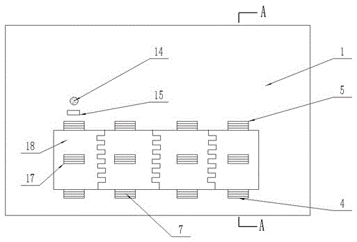
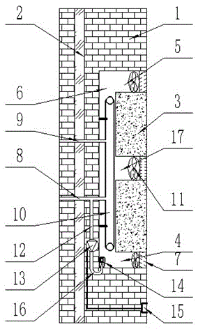
[0021] Example 1, such as figure 1 , image 3 As shown, a new type of heating wall includes a wall main body 1, a heat conduction layer 3 is embedded in the side of the wall main body 1 close to the indoor, and a gas passage 6 is provided between the heat conduction layer 3 and the wall main body 1, A heating device is fixedly installed in the gas passage 6, and the heating device includes a radiator main body 10, a water inlet pipe 8 and a water outlet pipe 9, and the water inlet pipe 8 and the water outlet pipe 9 are respectively connected to the radiator main body 10 , the heat conduction layer 3 includes four heat conduction blocks 18, the heat conduction blocks 18 are meshed with teeth, and each of the heat conduction blocks 18 is provided with an air outlet 5 and an air inlet 4 at the upper end and the lower end respectively. The upper end surface of the heat conduction block 18 is the lower end surface of the air outlet 5, the lower end surface of the heat conduction b...

Embodiment 2

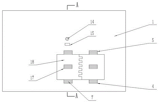
[0024] Example 2, such as figure 2 , image 3 As shown, a new type of heating wall includes a wall main body 1, a heat conduction layer 3 is embedded in the side of the wall main body 1 close to the indoor, and a gas passage 6 is provided between the heat conduction layer 3 and the wall main body 1, A heating device is fixedly installed in the gas passage 6, and the heating device includes a radiator main body 10, a water inlet pipe 8 and a water outlet pipe 9, and the water inlet pipe 8 and the water outlet pipe 9 are respectively connected to the radiator main body 10 , the heat conduction layer 3 includes two heat conduction blocks 18, the heat conduction blocks 18 are meshed with teeth, and the upper and lower ends of each heat conduction block 18 are respectively provided with two air outlets 5 and one two air outlets 4, so The upper end surface of the heat conduction block 18 is the lower end surface of the air outlet 5, the lower end surface of the heat conduction blo...


PUM


Abstract

A novel heating wall comprises a wall main body. A heat conduction layer is embedded into the side, close to a room, of the wall main body. An air passageway is arranged between the heat conduction layer and the wall main body. A heating device is fixedly mounted in the air passageway. The heating device comprises a heating radiator body, a water inlet pipe and a water outlet pipe. The upper end and the lower end of the air passageway correspondingly communicate with the room through exhaust openings and air inlets. A humidity adjusting system is arranged in the wall main body. The humidity adjusting system comprises a humidity sensor, a high-pressure pump and a spray nozzle. The water inlet end and the water outlet end of the high-pressure pump are correspondingly connected with the water outlet pipe and the spray nozzle. The humidity sensor is electrically connected with the high-pressure pump. By the adoption of the technical scheme, the novel heating wall has the beneficial effects that for the part needed to be overhauled, one or more heat conduction blocks can be disassembled in a targeted manner for overhauling without disassembling the whole heat conduction layer, the whole system is attractive in appearance, occupation to the space is avoided, persons close to the heating wall are not likely to be scalded, and meanwhile the indoor air can be humidified through the humidity adjusting system when dry.

Description

technical field [0001] The invention belongs to the field of residential heating systems, and in particular relates to a novel heating wall. Background technique [0002] With the development of social economy, more and more modern families incorporate heating as an essential device. At present, households usually use small mobile electric heaters, air conditioners, external wall heaters or floor heating. Mobile small electric heaters have an effective range. Small, large indoor temperature difference, dry air and other deficiencies; air conditioners are also electric heating, but there are disadvantages such as high power consumption, dry air and easy to cause diseases; external wall heating and floor heating are both plumbing equipment, which effectively solves the problem of high energy consumption and air pollution. Drying is not enough, but the external wall heating takes up a lot of space, is not beautiful, is not convenient for decoration, and is easy to burn people c...

Claims


Application Information

Patent Timeline
IPC IPC(8): F24D3/14F24D3/02F24D19/00F24D19/10
Inventor 不公告发明人
Owner CHONGQING WANSHENG FUSHENG DECORATION SHOP
Why Eureka
Try Eureka