Oil-pneumatic spring self-lubricating compensating floating piston

A floating piston, oil and gas spring technology, used in springs, springs/shock absorbers, gas-liquid shock absorbers, etc., can solve the problems of shortened service life, poor lubrication environment of sealing rings, and reduced reliability of oil and gas springs, so as to achieve extended Longevity, reduced friction, effect of a good lubricating environment

Active Publication Date: 2018-05-22
CHINA NORTH VEHICLE RES INST
View PDF7 Cites 0 Cited by
  • Summary
  • Abstract
  • Description
  • Claims
  • Application Information

AI Technical Summary

Problems solved by technology

Due to the high working pressure and the large difference in molecular volume between gas and oil, it is often necessary to use multiple sealing rings. Although this improves the sealing effect, it results in a poor lubricating environment for the middle sealing ring and the sealing ring on the gas side. It is easy to cause early wear of the sealing ring, which greatly shortens the service life and reduces the reliability of the oil and gas spring

Method used


Image

  • Oil-pneumatic spring self-lubricating compensating floating piston
  • Oil-pneumatic spring self-lubricating compensating floating piston
  • Oil-pneumatic spring self-lubricating compensating floating piston

Examples


Embodiment Construction

[0012] The present invention will be further described below in conjunction with accompanying drawings and examples.

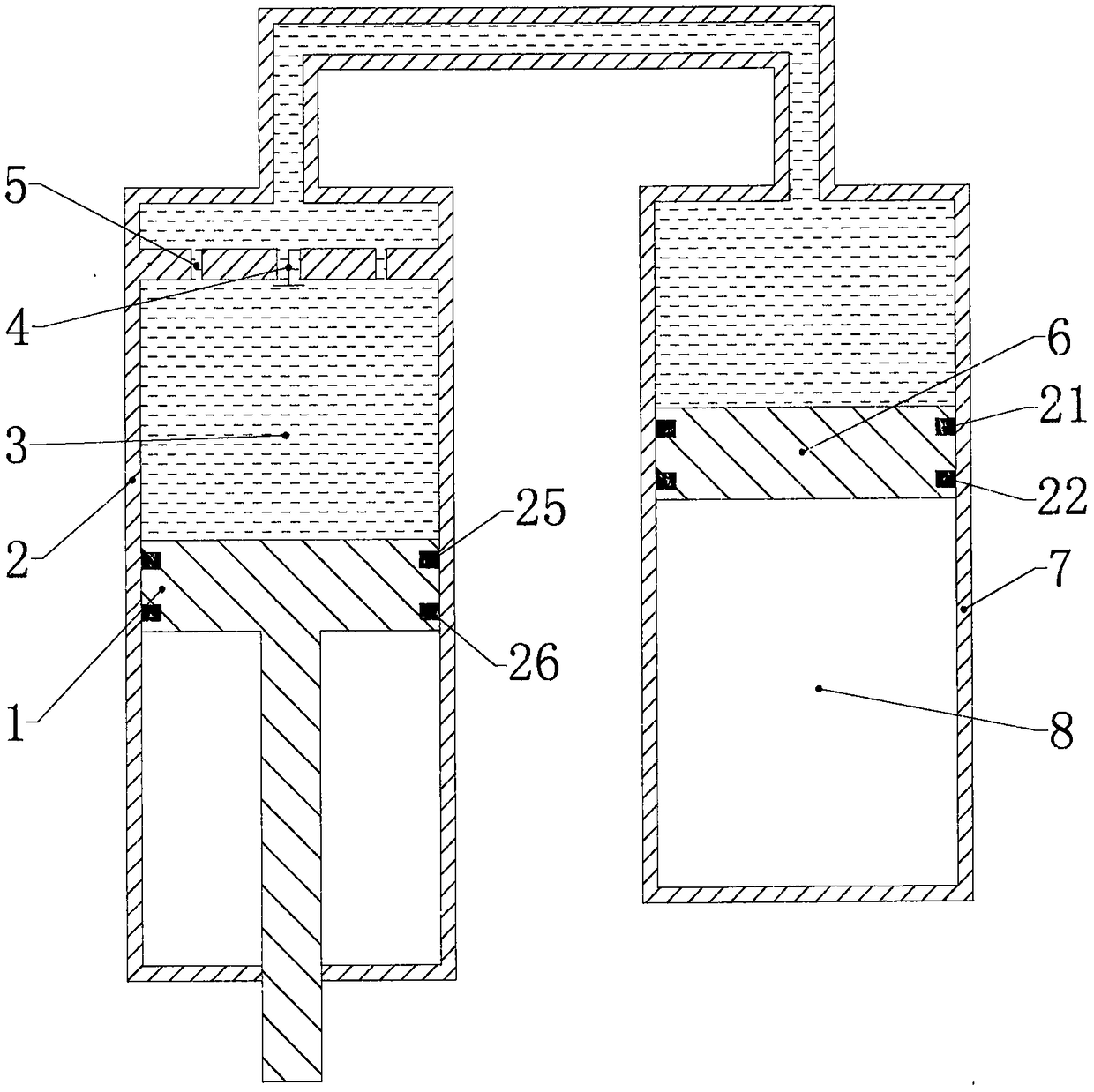
[0013] figure 1 It is a diagram of the working principle of the oil-gas spring. The inner cavities of the oil cylinder 2 and the cylinder 7 are connected together through the oil passage. The damping valve 4 and the main piston 1 are installed in the oil cylinder 2. A high-pressure combined oil seal is arranged on the main piston 1 for Seal the high-pressure oil 3 in the inner cavity, specific plan 1: a combination of two seals, in which the Ster seal is used as the first oil seal 25, which is arranged on the side close to the hydraulic oil, has a one-way sealing capability, and the sealing direction faces the oil side, the second oil seal 26 close to the side of the oil-gas spring annular chamber can use a gray ring, which has two-way sealing ability, and can also use a step seal with one-way sealing ability, and the sealing direction is towards the oil side....


PUM


Abstract

The invention aims at providing an oil and gas spring type self-lubricating compensation floating piston. The oil and gas spring type self-lubricating compensation floating piston comprises a small piston, an automatic lubricating floating piston, a small piston sealing ring and a clamp spring, wherein the small piston is sheathed in a center weight reducing groove of the automatic lubricating floating piston; lubricating oil or lubricating grease is arranged into an oil storage cavity surrounded by the small piston and the automatic lubricating floating piston; the small piston sealing ring is arranged in the small piston in the radial direction, and is matched with the inner wall of a weight reducing hole to form radial sealing; the clamp spring is arranged at the upper end of the weight reducing hole, so as to prevent the small piston from falling down from the automatic lubricating floating piston during high-speed movement; the side surface of the automatic lubricating floating piston is processed with a radial lubricating oil passage and a peripheral lubricating oil passage, a lubricating oil groove is arranged between a sealing ring at the oil side and a sealing ring at the gas side, and the lubricating oil passage is used for guiding the lubricating oil in the oil storage cavity into the lubricating oil tank and a radial gap between the automatic lubricating floating piston and a cylinder body.

Description

technical field [0001] The invention relates to a self-lubricating and compensating floating piston for an oil-gas spring, which belongs to the field of hydraulic machinery and vehicles. Background technique [0002] The oil-gas spring is a shock-absorbing device that uses inert gas (nitrogen) as the elastic medium, oil as the force transmission medium, and integrates elastic elements and damping elements. It exhibits very good nonlinear characteristics, and after installing the hydraulic electronic control system, it can also realize functions such as vehicle attitude adjustment and suspension rigid locking. Compared with other suspension systems, oil-pneumatic suspension can fully improve the vehicle's maneuverability, comfort and handling stability, especially to meet the index requirements of special vehicles, engineering vehicles and military vehicles, and has a good development prospect. [0003] The high-pressure combined seal is an important part of the oil-gas spri...

Claims


Application Information

Patent Timeline
Patent Type & Authority Patents(China)
IPC IPC(8): F16F9/06F16F9/32F16F9/36
CPCF16F9/06F16F9/3207F16F9/3214F16F9/3278F16F9/36
Inventor 毛明陈轶杰桂鹏张旭杜甫张亚峰高晓东韩小玲徐梦岩鞠海洁宁丹
Owner CHINA NORTH VEHICLE RES INST
Why Eureka
Try Eureka