Rotor, electric machine including same, and method for producing rotor

A rotor and rotor shaft technology, applied in the field of rotors, can solve the problems of wire loosening and breakage, and achieve the effect of high mechanical stability

Active Publication Date: 2017-06-13
ROBERT BOSCH GMBH
View PDF11 Cites 10 Cited by
  • Summary
  • Abstract
  • Description
  • Claims
  • Application Information

AI Technical Summary

Problems solved by technology

There is thus the risk that the conductors of

Method used


Image

  • Rotor, electric machine including same, and method for producing rotor
  • Rotor, electric machine including same, and method for producing rotor
  • Rotor, electric machine including same, and method for producing rotor

Examples


Embodiment Construction

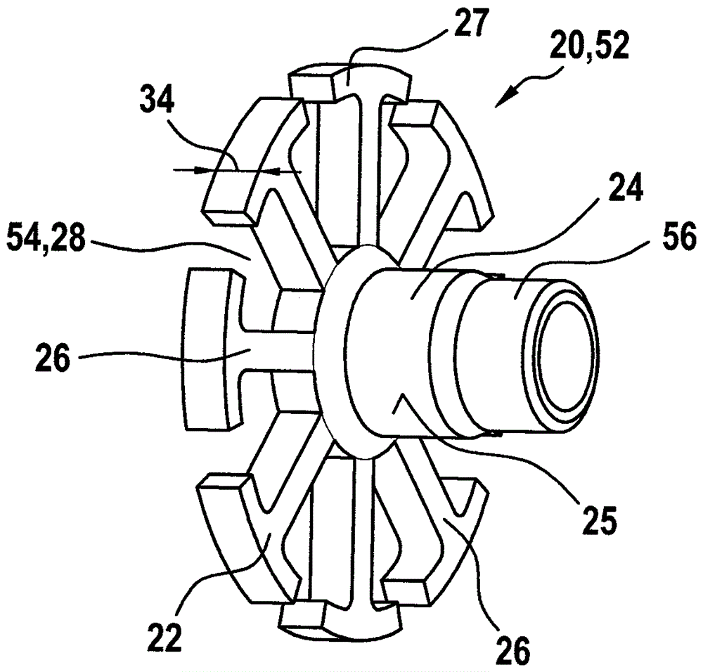
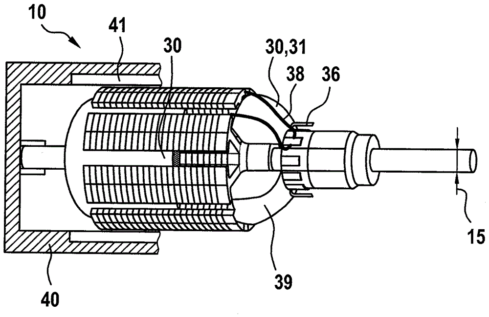
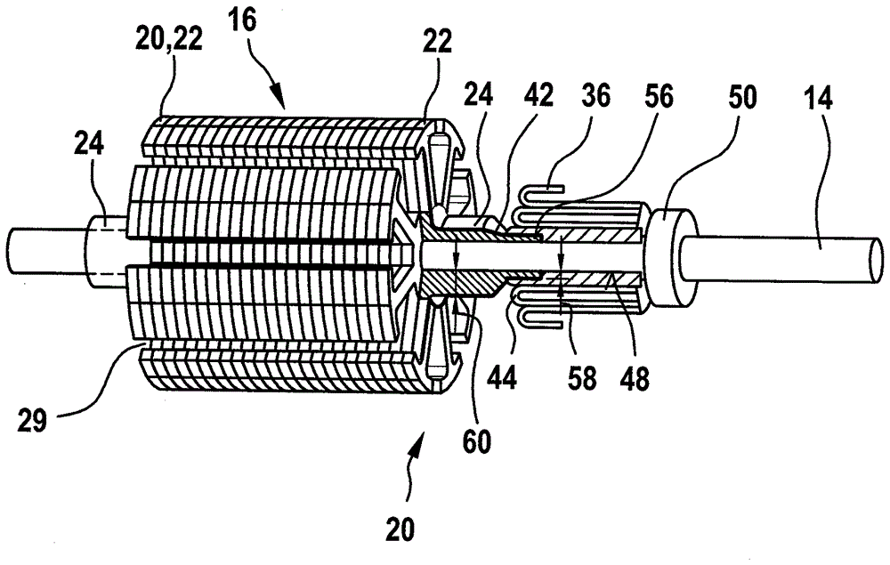
[0024] exist figure 1 A rotor 12 of an electric machine 10 is shown in , wherein a rotor set 16 is arranged on a rotor shaft 14 . The rotor group 16 consists of individual metal plates 18 stacked one above the other, which each have an end piece 20 at the axial ends of the rotor group 16 . The metal plates 18 are usually punched out of electrical sheet steel and have radial rotor teeth 26 with slots 28 in between. A tooth head 27 is formed on the radially outer end of the rotor tooth 26 , which radially covers part of the groove 28 . The plates 18 stacked one above the other together with the end pieces 20 have longitudinal grooves 29 according to figure 2 The rotor winding 30 shown in the figure is accommodated in the longitudinal slots. The end plate 20 is likewise produced from a magnetically conductive metal and has a plate body 22 to which a sleeve 24 is connected in the axial direction. In this exemplary embodiment, the sleeve 24 is formed together with the laminati...


PUM


Abstract

The invention relates to a rotor and an electric machine (10) in particular for the motorized adjustment of a movable part in a motor vehicle, and a method for producing such the rotor. The rotor comprises a rotor shaft (14), a rotor assembly (16) for containing a rotor winding (30) is fixed to the rotor, and the rotor assembly (16) comprises an end plate (20) made of metal. The rotor is characterized in that at least one end plate (20) comprises a sleeve (24) made of metal, and the sleeve extends along the axial direction from a disk-shaped plate body (22) of the end plate (20) and encloses the rotor shaft (14).

Description

technical field [0001] The invention relates to a rotor of the type according to the independent claims, an electrical machine comprising the rotor and a method for manufacturing the rotor. Background technique [0002] A direct-current motor is already known from EP 0 895 668 B1, in which the lamination pack is fixed on the armature shaft. After assembly of the lamination, the lamination is coated with epoxy resin which insulates the armature group from the winding wires. For its fixing, the commutator is pressed axially against the epoxy on the armature shaft, so that after cooling a form-locking connection is formed. [0003] In such electric motors, bending of the armature shaft can occur due to external loads, especially when thin armature shafts are used. As a result, there is a risk that the conductors of the armature winding will loosen and / or break. Contents of the invention [0004] On the other hand, the rotor according to the invention, the electric machine ...

Claims


Application Information

Patent Timeline
IPC IPC(8): H02K13/00H02K1/26H02K15/02
CPCH02K1/265H02K13/006H02K15/02H02K1/28H02K15/12
Inventor B.蒙齐H.莱默J.赫尔普J.哈尔夫曼L.瓦格纳
Owner ROBERT BOSCH GMBH
Why Eureka
Try Eureka