U-shaped housing device provided with side wall pipeline structure of water purifier

A water purifier, U-shaped technology, applied in water/sewage treatment equipment, water/sewage treatment, water/sludge/sewage treatment, etc., can solve the problem that water purifiers are difficult to be widely popularized, and avoid inconvenience and service expenditures, reduce usage costs, and facilitate remote users

Active Publication Date: 2017-07-07
杜也兵
View PDF10 Cites 4 Cited by
  • Summary
  • Abstract
  • Description
  • Claims
  • Application Information

AI Technical Summary

Problems solved by technology

Above-mentioned defect and deficiency cause water purifier to be difficult to obtain wider popularization

Method used


Image

  • U-shaped housing device provided with side wall pipeline structure of water purifier

Examples


Embodiment 1

[0019] Example 1. The machine includes a U-shaped housing and upper cover for accommodating and placing multiple filter galls, an electric control water passing part and a swing lock hook device; each filter gall is connected and fixed in the U-shaped shell by a filter gall fastening device, and each filter gall The water outlet of the U-shaped housing is sealed and docked with the corresponding docking water outlet of the water passage on the bottom surface of the U-shaped housing, and the electric control water passage components are connected at relevant places to form a filter channel. The swing locking hook device includes a swing shaft, a swing shaft support, a swing hook plate and a lock hook structure; the first part of the U-shaped housing and the upper cover is provided with a swing shaft and a swing shaft support, and the second part is provided with a lock hook structure The swing lock hook device may adopt a single-axis swing lock hook structure in which one end o...

Embodiment 2

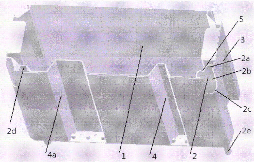
[0024] Example 2. On the basis of embodiment 1, the machine can also be provided with a maintenance base device; the electric control water passing component in the machine filter channel is placed on the maintenance base device; the U-shaped housing is provided with a vertical gallbladder cavity and The single-layer cavity structure of the pipeline structure; the U-shaped shell is in contact with the upper and lower maintenance base devices and is connected and fixed by the fastening device. The fastening device comprises brackets with pin holes respectively located on the two parts, pins which are plugged and fitted with the pin holes on the respective brackets of the two parts, and the above-mentioned swing lock hook device. The control wires of the electrically controlled water passing parts on the maintenance base device are led to the upper part of the U-shaped housing through the pipeline structure provided on the side wall of the U-shaped housing. The U-shaped housing...

Embodiment 3

[0027] Example 3. On the basis of Embodiment 1, the machine can also be provided with a maintenance base device; place the electronically controlled water passing components in the filter channel of the machine on the maintenance base device. As the first U-shaped shell structure model in this example, the U-shaped shell is a double-layer cavity structure with a lateral movement channel in the lower part and a vertical bile filter cavity and pipeline structure in the upper part. The maintenance base device is inserted along the lateral movement channel. The bottom of the vertical gallbladder cavity is plugged and fitted with the U-shaped housing, and is connected and fixed as a whole with a fastening device. The fastening device includes fastening standard parts such as screw and nut assemblies acting between the maintenance base device and the U-shaped housing, and the above-mentioned swing lock hook device. The control wires of the electrically controlled water passing part...


PUM


Abstract

The invention relates to the water treatment industry, in particular to drinking water filtration.The invention discloses a U-shaped housing device provided with a side wall pipeline structure of a water purifier.The device comprises a U-shaped housing for accommodating and placing a plurality of filtration liners, an upper cover and a swing lock hook device, wherein eachfiltration liner isconnected withand fixed in the U-shaped housing via a filtration liner fastening device; water gaps of the filtration liners are in butt joint with butting water gaps of water through pipelines on the bottom surface of the U-shaped housing in a sealing manner to form a filtration channel; the upper cover is ofa siding structure or a flip structure; the swing lock hook device connects the U-shaped housing with the upper cover to form an enclosed filtration liner cabin; the upper cover is moved after the swing lock hook device is opened; the device further comprises the pipeline structure arranged on the outer side of a cavity wall of the U-shaped housing; and the pipeline structure is at least one of an overflow pipeline structure or a guide pipeline structure and is integrally formed with the U-shaped housing.

Description

technical field [0001] The invention relates to the water treatment industry, and specifically relates to the deep filtration and purification of drinking water. Background technique [0002] The horizontal water purifier can be placed on the countertop of the kitchen cabinet or in the cabinet. You only need to place the machine directly on the place of use. There is no need to drill holes to hang the machine, so it is very convenient to use. Because the filter gall is located above the machine base, it is more convenient to replace the filter gall, which is relatively time-saving and labor-saving. However, the biggest problem with the structure of the seat type water purifier is that the operating surface of the machine is small, the display window and the operation control device can only be installed on the side elevation of the machine, and the top surface is used to replace the filter bladder, and there is nowhere to put the parts. In view of the limited length and wid...

Claims


Application Information

Patent Timeline
Patent Type & Authority Applications(China)
IPC IPC(8): C02F1/00
CPCC02F1/00C02F2201/002
Inventor 杜也兵冉伊虹
Owner 杜也兵
Why Eureka
Try Eureka