An Adaptive Controllable Electromagnetic Damper

An electromagnetic damper and self-adaptive technology, applied in the field of shock absorbers, can solve problems such as poor controllability of dampers and limit devices, energy consumption capacity, non-adjustable limit requirements, and inability to realize active control, etc., to achieve increased Large energy consumption capacity, realize the effect of active control

Active Publication Date: 2018-12-14
SOUTHEAST UNIV
View PDF6 Cites 0 Cited by
  • Summary
  • Abstract
  • Description
  • Claims
  • Application Information

AI Technical Summary

Problems solved by technology

At present, the existing energy-dissipating devices and limiting devices of dampers still have deficiencies: passive energy-dissipating shock absorption, energy-dissipating capacity, and limiting requirements cannot be adjusted; and can only make full use of the energy-dissipating properties of its own materials to achieve maximum energy consumption ability, the controllability of the damper and the limit device itself is poor, and it is difficult to apply to various levels of structural shock absorption control
At present, dampers using electromagnetic effects have been applied, such as "semi-controllable cylindrical linear electromagnetic damper", "a kind of rotor vibration active control electromagnetic damper", "an electromagnetic damper", "with bearing Electromagnetic damper", but it is mainly used in the field of motor technology, and mainly to make full use of the material properties of the shock absorber itself, it cannot realize energy consumption adjustment, and cannot realize active control

Method used


Image

  • An Adaptive Controllable Electromagnetic Damper
  • An Adaptive Controllable Electromagnetic Damper
  • An Adaptive Controllable Electromagnetic Damper

Examples


Embodiment Construction

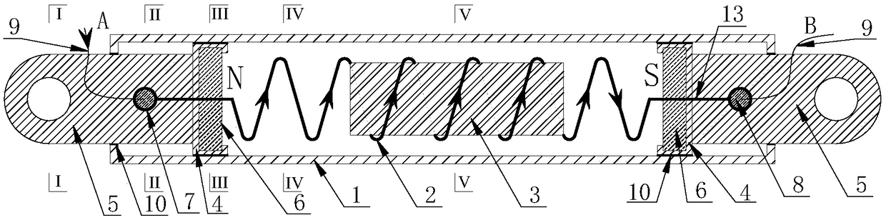
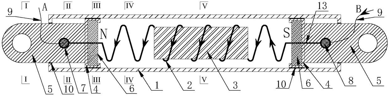
[0030] The technical solution of the present invention will be further described below in conjunction with the accompanying drawings.

[0031] like figure 1 and figure 2 As shown, the present invention discloses an adaptive controllable electromagnetic damper, comprising a damping outer cylinder 1, a spring 2, an iron core 3, a piston 4, a piston rod 5, a permanent magnet 6, an insulating sleeve 7, an anchor head 8, a wire 9. Rubber gasket 10, support rod 11, stop plate 12 and connecting piece 13.

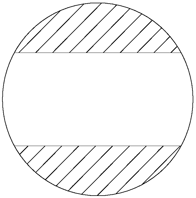
[0032] like Figure 8 and Figure 9 As shown, the spring 2 is evenly wound around the periphery of the iron core 3, and there is a gap between the iron core 3 and the spring 2; the support rods 11 are symmetrically and evenly distributed in the middle position of the spring 2, and the two ends of the iron core 3 are provided with stoppers. The baffle plate 12 , the support rod 11 and the stop plate 12 limit the iron core 3 to freely hang in the middle position of the spring 2 . ...


PUM


Abstract

The invention discloses a self-adaption controllable electromagnetic damper. The self-adaption controllable electromagnetic damper comprises a damping external cylinder, an iron core located in the middle of an inner cavity of the damping external cylinder and sleeved with a spring and piston assemblies located at the two ends of the damping external cylinder correspondingly, each piston assembly comprises a piston arranged in the inner cavity of the damping external cylinder and capable of moving in the axial direction of the inner cavity of the damping external cylinder in a reciprocating mode, a piston rod with one end connected with the corresponding piston and the other end penetrating out of the damping external cylinder and a permanent magnet arranged in the corresponding piston, and an enclosed space is formed among the piston assemblies and the inner wall of the damping external cylinder; and the piston rods are internally provided with anchor heads with the peripheries sleeved with insulation sleeves, the two ends of the spring penetrate through the permanent magnets correspondingly and are fixed to the corresponding anchor heads, the anchor heads at the two ends are connected with an electromagnetic control system by means of the method that wires are led out from the anchor heads correspondingly, and the two conducting ends are formed.

Description

technical field [0001] The invention relates to a shock absorbing damper, which belongs to the shock absorbing control technology of structures such as bridges and houses in the field of civil engineering, and in particular relates to an adaptive controllable electromagnetic damper. Background technique [0002] my country is located in the Pacific Rim Seismic Belt - the Eurasian Seismic Belt, where earthquakes occur frequently. Over the past ten years, there have been more than 500 earthquakes of magnitude 5 or above. unbearable loss. It is the key to ensure the safety of people's lives and property to develop new shock-absorbing and isolating devices to enhance the seismic performance of buildings and bridge structures. [0003] With the continuous emergence of super-high, super-long-span buildings and long-span bridges, structural shock-absorbing and isolation devices have been fully developed and applied, and have achieved good shock-absorbing and isolation effects. In o...

Claims


Application Information

Patent Timeline
Patent Type & Authority Patents(China)
IPC IPC(8): F16F6/00
CPCF16F6/00
Inventor 王浩郑文智茅建校邹仲钦沙奔张玉平
Owner SOUTHEAST UNIV
Why Eureka
Try Eureka