High-speed micro hole punching die

A micro-hole die and high-speed stamping technology, which is applied to punching machines, piercing tools, presses, etc., can solve problems such as time-consuming and labor-intensive, easy wear of cylinders and oil cylinders, and slow processing speed.

Pending Publication Date: 2017-10-10
昆山钣源冲压技术有限公司
View PDF0 Cites 4 Cited by
  • Summary
  • Abstract
  • Description
  • Claims
  • Application Information

AI Technical Summary

Problems solved by technology

[0002] During the processing of existing molds, the processing speed is slow, and it is necessary to repeatedly install the parts to be stamped on the lower mold base, which is time-consuming and laborious. Moreover, most of the existing stamping molds are stamped by air cylinders or oil cylinders. The stamping speed is slow and repeated actions are required. Cylinders and oil cylinders are also easy to wear, and the stamping speed is slow. For this reason, we propose a high-speed stamping microporous die

Method used


Image

  • High-speed micro hole punching die
  • High-speed micro hole punching die
  • High-speed micro hole punching die

Examples


Embodiment Construction

[0016] The technical solutions in the embodiments of the present invention will be clearly and completely described below with reference to the accompanying drawings in the embodiments of the present invention. Obviously, the described embodiments are only a part of the embodiments of the present invention, but not all of the embodiments.

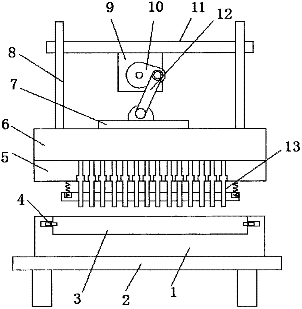
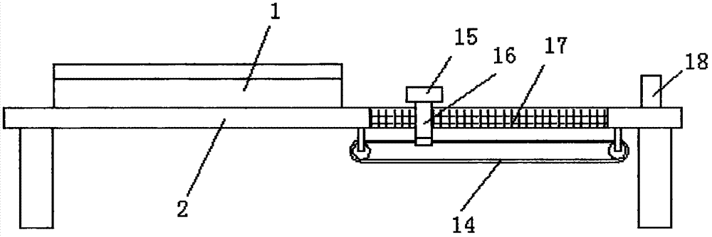
[0017] refer to Figure 1-3 , a high-speed stamping microporous die, including a base 2 and a fixing plate 11, the bottom end of the base 2 is welded with support columns, the top of the base 2 is provided with a fixing plate 11, and the top side of the base 2 is fixed with a lower die seat 1. The top of the lower die base 1 is provided with a punching slot 3, and the side walls on both sides of the punching slot 3 are provided with installation slots. The interior of the installation slot is rotatably connected with a plurality of guide wheels 4. The bottom end of the base 2 is a A horizontally arranged conveyor belt 14 is installed on the...


PUM


Abstract

The invention discloses a high-speed micro hole punching die. The high-speed micro hole punching die comprises a base and a fixing plate; a supporting column is welded to each of the four corners of the bottom end of the base; the fixing plate is arranged above the base; a lower die base is fixed to one side of the top end of the base; a hole punching groove is formed in the top end of the lower die base; the side walls of the two sides of the hole punching groove are each provided with an installing groove; a plurality of guiding wheels are rotationally connected in each installing groove; a horizontally arranged conveying belt is arranged on one side of the bottom end of the base; a first through hole is formed above the conveying belt and is located in the base; a connecting column is fixed to the side wall of the top end of the conveying belt through a screw; the top end of the connecting column penetrates the first through hole and is connected with a clamping device; the connecting column is in sliding connection with the side wall of the first through hole; the clamping device is arranged at the top end of the connecting column; and the side, away from the lower die base, of the first through hole is provided with a supporting block. The high-speed micro hole punching die can drive a to-be-punched part to fast move on the lower die base, punching is convenient, punches on an upper die base can be driven to fast and repeatedly to perform downward punching, and the punching speed is high.

Description

technical field [0001] The invention relates to the technical field of molds, in particular to a high-speed punching microporous mold. Background technique [0002] During the processing of the existing dies, the processing speed is slow, and the parts to be stamped need to be repeatedly installed on the lower die base, which is time-consuming and labor-intensive, and most of the existing stamping dies are punched by air cylinders or oil cylinders, and the punching speed is slow and requires repeated actions. Cylinders and oil cylinders are also easy to wear and the stamping speed is slow. For this reason, we propose a high-speed stamping micro-hole die. SUMMARY OF THE INVENTION [0003] The purpose of the present invention is to propose a high-speed punching microporous die in order to solve the shortcomings existing in the prior art. [0004] In order to achieve the above object, the present invention adopts the following technical solutions: [0005] A high-speed punc...

Claims


Application Information

Patent Timeline
IPC IPC(8): B21D28/24B21D28/34B30B1/26
CPCB21D28/24B21D28/34B30B1/26
Inventor 宋功艮
Owner 昆山钣源冲压技术有限公司
Why Eureka
Try Eureka