Equipment state monitoring system and monitoring method

A technology for equipment status and monitoring systems, applied in the field of monitoring systems, can solve problems such as expensive, inability to monitor mechanical faults, and complex analysis and processing processes, and achieve the effects of simple and easy-to-use structure, simplified monitoring process, and improved management efficiency

Inactive Publication Date: 2017-10-24
BEIJING MECHANICAL EQUIP INST
View PDF8 Cites 1 Cited by
  • Summary
  • Abstract
  • Description
  • Claims
  • Application Information

AI Technical Summary

Problems solved by technology

[0006] In view of the above analysis, the present invention aims to provide an equipment status monitoring system and monitoring method, which solves the problems in the prior art that the equipment status monitoring system structure and analysis and processing process are complex, expensive, and unable to monitor mechanical failures

Method used


Image

  • Equipment state monitoring system and monitoring method
  • Equipment state monitoring system and monitoring method

Examples


Embodiment 1

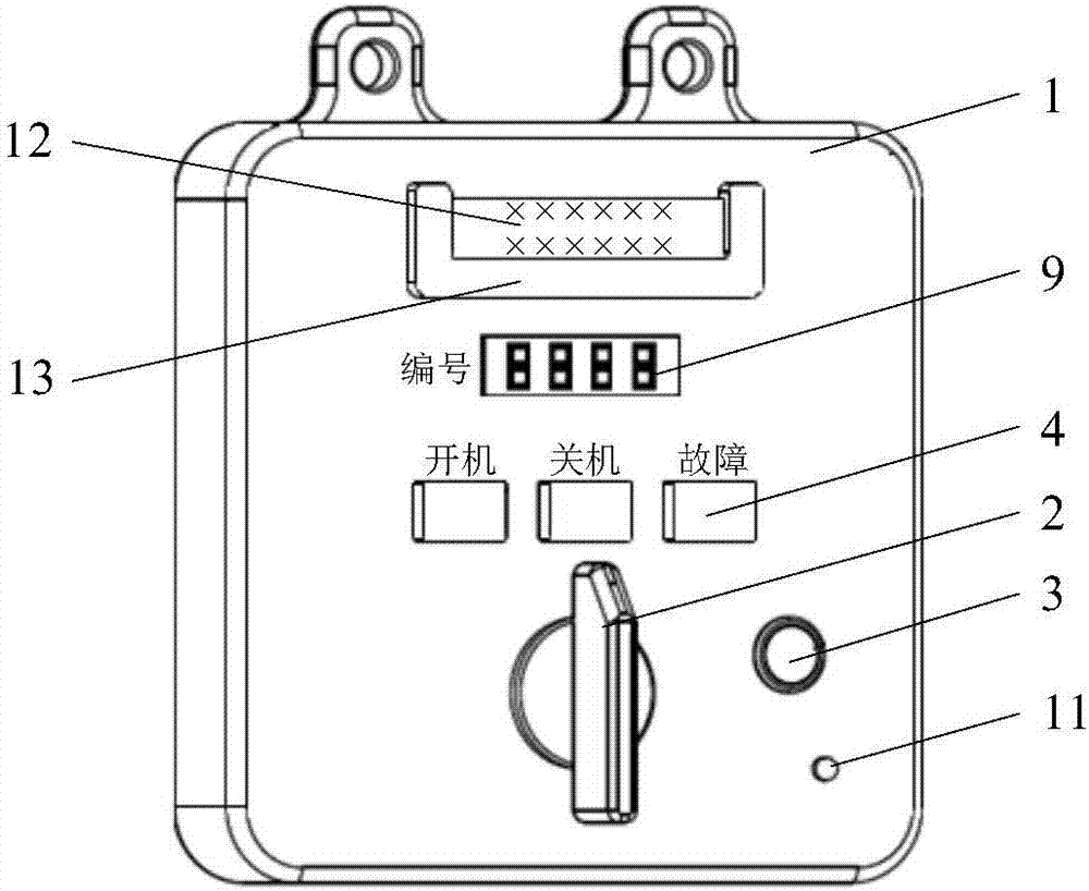
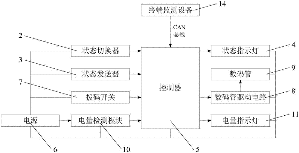
[0033] This embodiment provides a monitoring system for equipment status, see Figure 1 to Figure 2 , which includes a housing 1, a status switcher 2, a status transmitter 3, a status indicator light 4, a controller 5 and a power supply 6, wherein the status switcher 2, the status transmitter 3 and the status indicator light 4 are arranged in the housing 1 The controller 5 and the power supply 6 are located inside the casing 1 . The power supply 6 supplies power for the state switcher 2, the state transmitter 3, the state indicator light 4 and the controller 5; the controller 5 obtains the equipment status data collected by the monitoring personnel through the status switcher 2; the controller 5 identifies the equipment status data and controls the status The indicator light 4 displays the corresponding device status, and the status transmitter 3 sends a status data sending instruction to the controller 5, and the controller 5 sends the status data to the terminal monitoring s...

Embodiment 2

[0047] This embodiment provides a method for monitoring equipment status, including the following steps:

[0048] S1: The controller obtains the device status of multiple devices collected by the monitoring personnel through the status switcher;

[0049] The controller obtains the DIP data of the DIP switch;

[0050] The controller obtains the power data of the power supply through the power monitoring module;

[0051] S2: The controller identifies the device status data and controls the status indicator to display the corresponding device status; the status transmitter sends the status data sending instruction to the controller, and the controller sends the status data to the terminal monitoring system according to the sending instruction;

[0052] The controller identifies the dialing data of the dialing switch, and the recognized dialing data is displayed on the digital tube through the digital tube drive circuit, so that the dialing tube displays the number corresponding ...


PUM


Abstract

The invention relates to an equipment state monitoring system and monitoring method, and belongs to the technical field of monitoring system. The equipment state monitoring system includes a housing, a state switcher, a state transmitter, a state indicating lamp, a controller and a power supply, wherein the state switcher, the state transmitter and the state indicating lamp are arranged on the surface of the housing; the controller and the power supply are arranged in the housing; the power supply supplies power for the state switcher, the state transmitter, the state indicating lamp and the controller; the controller acquires the equipment state data acquired by monitoring staff through the state switcher; the controller identifies the equipment state data and controls the state indicating lamp to display the corresponding equipment state; the state transmitter transmits a transmitting command of the state data to the controller; and the controller transmits the state data to a terminal monitoring system according to the transmitting command. The equipment state monitoring system can be used for monitoring the equipment state.

Description

technical field [0001] The invention relates to a monitoring system, in particular to an equipment status monitoring system and a monitoring method. Background technique [0002] With the development of science and technology, the functions that equipment needs to realize tend to be diversified and complicated, and correspondingly, equipment has more and more components. [0003] In the prior art, computers and sensors are usually used to monitor equipment status. [0004] However, the structures and analysis processes of the above-mentioned computers and sensors are complex and expensive, so that they can only be applied to important equipment in the system, but cannot monitor all equipment. Especially in the case of a large number of devices in the system, the use of computers and sensors to monitor the status of all devices is more expensive, making it impossible to apply in actual work. [0005] In addition, computers and sensors are usually only able to collect and mo...

Claims


Application Information

Patent Timeline
Patent Type & Authority Applications(China)
IPC IPC(8): G05B19/042
CPCG05B19/0428G05B2219/24024
Inventor 董洪川宋志强孙磊王超然韩士玉
Owner BEIJING MECHANICAL EQUIP INST
Why Eureka
Try Eureka