Cooking utensil

A technology for cooking utensils and cooking chambers, applied in kitchen utensils, home utensils, roasters/barbecue grids, etc., can solve problems such as incompetence, fast heating, slow cooking, etc. The effect of uniform field distribution and satisfying cooking needs

Inactive Publication Date: 2017-11-28
GUANGDONG MIDEA KITCHEN APPLIANCES MFG CO LTD +1
View PDF6 Cites 20 Cited by
  • Summary
  • Abstract
  • Description
  • Claims
  • Application Information

AI Technical Summary

Problems solved by technology

When the food is close to the heating element, the heating speed is fast but the uniformity is poor
Some parts of the food are burnt and some parts are not cooked; when the distance between the food and the heating element is farther, the coloring of the food is more uniform, but the cooking speed is slower
[0005] 2) Electric oven with hot air function, its hot air function is not obvious, the wind speed is small, and the uniformity is poor
However, its complex structure and large size are not suitable for home use.
A horizontal gas jet impingement oven is also disclosed in the related art. Only the upper part of the oven is equipped with nozzles, which can directly heat and color the upper surface of the food (near the nozzle), while the lower surface of the food is heated by the impact of gas to the bottom of the cavity. It is carried out by reflection, and there is a problem of uneven coloring on the top and bottom of the food
In addition, the distance between the nozzle and the grill is only 70mm, which cannot be used to complete common family menus such as roast chicken and cakes
[0009] To sum up, the electric oven in the related art has the problems of complex equipment structure, poor heating uniformity, and small space, so it cannot be used for menus such as roast chicken and cakes.

Method used


Image

  • Cooking utensil
  • Cooking utensil
  • Cooking utensil

Examples


Embodiment Construction

[0049] In order to understand the above objects, features and advantages of the present invention more clearly, the present invention will be further described in detail below with reference to the accompanying drawings and specific embodiments. It should be noted that the embodiments of the present application and the features in the embodiments may be combined with each other in the case of no conflict.

[0050] Many specific details are set forth in the following description to facilitate a full understanding of the present invention. However, the present invention can also be implemented in other ways different from those described herein. Therefore, the protection scope of the present invention is not limited by the specific details disclosed below. Example limitations.

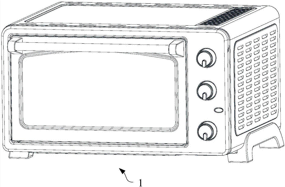
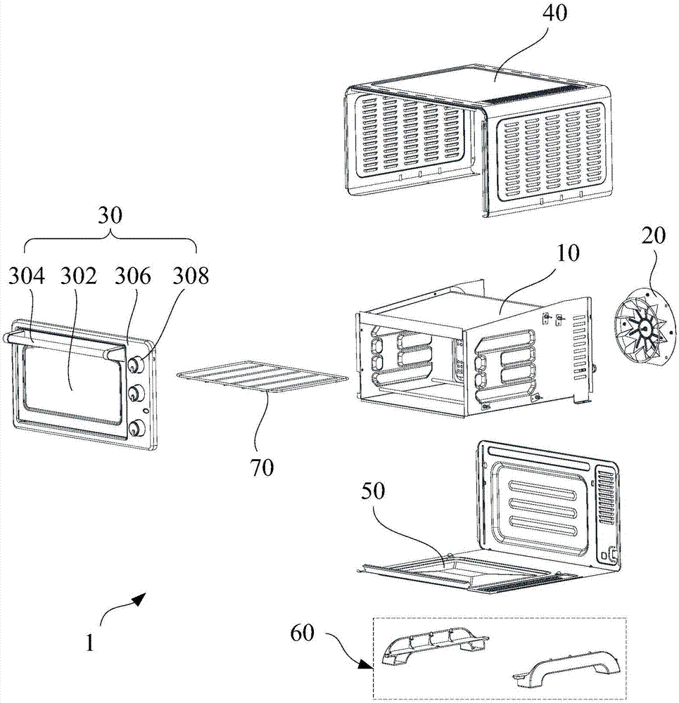
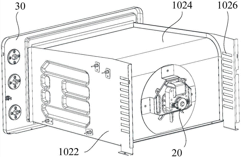
[0051] Refer below Figure 1 to Figure 12 The cooking appliance 1 according to some embodiments of the present invention is described.

[0052] like Figure 1 to Figure 5 , Figure 8 As shown, the em...


PUM


Abstract

The invention provides a cooking utensil. The cooking utensil comprises a cavity assembly, a fan assembly and a door body assembly, wherein the cavity assembly comprises a shell and a jet orifice plate positioned in the shell, the shell forms a cavity with an opening at the front end, the jet orifice plate comprises a jetting section and an air return section which are connected with each other, one of the jetting section and the air return section extends backwards along the top wall or the bottom wall from the front end of the shell, the other one of the jetting section and the air return section extends along the vertical direction, a plurality of spray nozzles are distributed on the jetting section, air return openings are formed in the air return section, the jet orifice plate separates the cavity into an air duct and a cooking cavity, the spray nozzles and the air return openings communicate with the air duct and the cooking cavity, a first heating element is arranged in the air duct, a second heating element is arranged in the cooking cavity, and the second heating element and the jetting section are arranged oppositely; the fan assembly comprises a motor and first blades driven by the motor to rotate, and the first blades are positioned in the air duct; the door body assembly covers the opening for opening and closing the cooking cavity. For the cooking utensil provided by the invention, the heating is rapid and uniform, the structure is simple, and the size is moderate.

Description

technical field [0001] The invention relates to the technical field of kitchen appliances, in particular to a cooking utensil. Background technique [0002] An electric oven is a common kitchen appliance. Unlike microwave heating, electric ovens retain the moisture and nutrients contained in food. [0003] At present, the main types of electric ovens on the market are electric ovens without hot air function and electric ovens with hot air function: [0004] 1) For an electric oven without a hot air function, a number of heating elements are installed in the cavity of the electric oven to heat food through heat radiation. The commonly used heating elements include metal heating tubes, quartz heating tubes, halogen heating tubes, etc. Because the heat of the heating element is transferred around in a radiative manner, it is based on this heat transfer characteristic. When the food is close to the heating element, the heating speed is fast but the uniformity is poor. Some ...

Claims


Application Information

Patent Timeline
Patent Type & Authority Applications(China)
IPC IPC(8): A47J37/06
CPCA47J37/0629A47J37/0641
Inventor 孙炎军黄志飞陈茂顺
Owner GUANGDONG MIDEA KITCHEN APPLIANCES MFG CO LTD
Why Eureka
Try Eureka