Prefabricated plate beam erecting method

A prefabricated panel and truss technology, applied in bridge construction, erection/assembly of bridges, bridges, etc., can solve the problems of high use and rental costs, cumbersome installation and disassembly process, affecting the speed of bridge erection, etc., to save construction period and erection process. Simple and convenient effects

Inactive Publication Date: 2017-12-08
THE 2ND ENG CO LTD MBEC +1
View PDF6 Cites 3 Cited by
  • Summary
  • Abstract
  • Description
  • Claims
  • Application Information

AI Technical Summary

Problems solved by technology

[0003] In the process of bridge construction, in order to shorten the construction period of the entire bridge and interfere with the site environment during the bridge construction process, prefabricated slab girder bridges are widely used. For the installation of prefabricated slab girders, special large-scale bridging equipment is required and cranes, and the bridge construction site is often unable to provide enough space for the arrangement of special large-scale bridging equipment and cranes due to site and environmental constraints, and the installation and disassembly process of special large-scale bridging equipment is cumbersome, costly to use and rent Higher, affects the erection speed of the entire bridge, and also greatly increases the bridge construction cost

Method used


Image

  • Prefabricated plate beam erecting method
  • Prefabricated plate beam erecting method
  • Prefabricated plate beam erecting method

Examples


Embodiment Construction

[0042] The present invention will be described in further detail below in conjunction with the accompanying drawings.

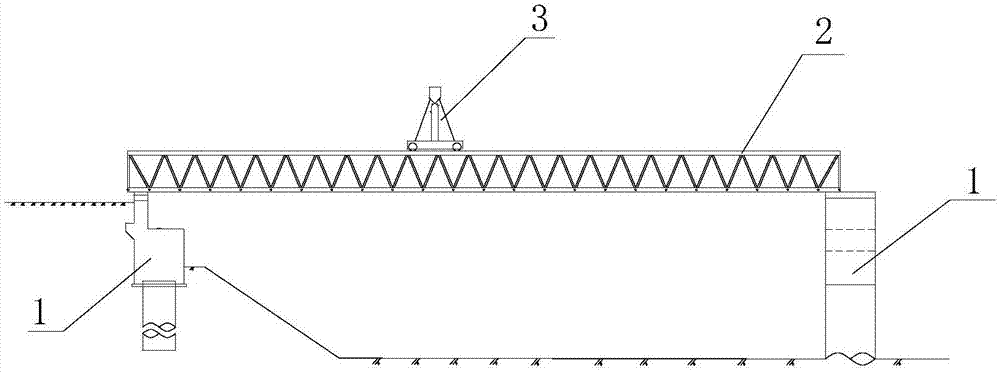
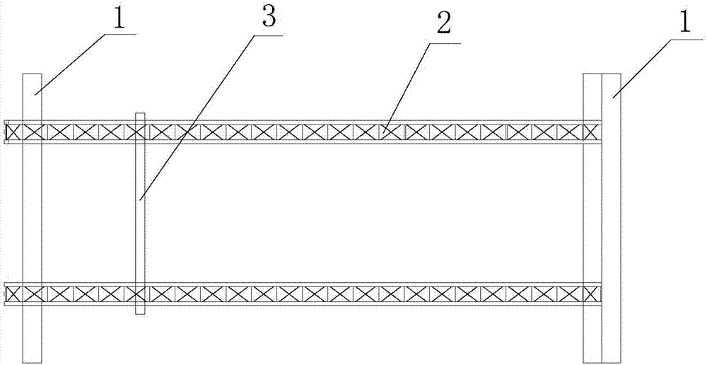
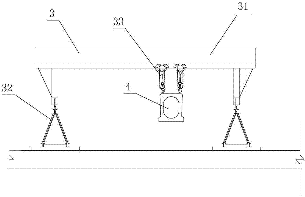
[0043] The present invention provides a method for erecting a prefabricated slab girder, which is used for the construction of a bridge whose deck is a prefabricated slab girder 4. Specifically, during the erection process of the prefabricated slab girder 4, the prefabricated slab girder 4 is moved along the bridge construction direction from the first The first position is moved to the second position and positioned. In actual erection, after the erection of the prefabricated slab girder 4 is completed, the prefabricated slab girder 4 is located on a span of the bridge, that is, one end of the prefabricated slab girder 4 is located in the adjacent pier 1 On one pier 1, the other end is located on another pier 1 among the adjacent pier 1, and the construction direction is from the bridge head to the center of the bridge when the bridge is erected. The second ...


PUM


Abstract

The invention discloses a prefabricated plate beam erecting method, and relates to the field of prefabricated plate beam installation construction. The prefabricated plate beam erecting method comprises the steps that S1, two parallel trusses are arranged on two adjacent bridge piers along the direction of a bridge, meanwhile a track used for allowing a beam-shifting trolley to walk is arranged on the top faces of the two trusses, and the beam-shifting trolley is erected on the track; S2, a beam transporting vehicle transports a prefabricated plate beam to a first position, and the prefabricated plate beam is kept to be parallel to the bridge direction; S3, the beam-shifting trolley hoists the prefabricated plate beam to be close to one end of a second position, and meanwhile the prefabricated plate beam and the beam-shifting trolley are driven to move together along the direction of the bridge till the prefabricated plate beam reaches to the second position; S4, the prefabricated plate beam is placed on the second position; and S5, a next prefabricated plate beam is transported by the beam transporting vehicle to the first position, and the step S2, the step S3 and the step S4 are circulated till construction of all prefabricated plate beams of the two adjacent bridge piers is completed. According to the prefabricated plate beam erecting method, construction is convenient, and using of large bridging hoisting equipment in the bridge erecting process is effectively reduced.

Description

technical field [0001] The invention relates to the field of installation and construction of prefabricated slab girders, in particular to a method for erecting prefabricated slab girders. Background technique [0002] With the rapid development of highway and municipal engineering construction in our country, bridges are used more frequently, especially in the process of highway municipal construction, more and more bridges are under construction. [0003] In the process of bridge construction, in order to shorten the construction period of the entire bridge and interfere with the site environment during the bridge construction process, prefabricated slab girder bridges are widely used. For the installation of prefabricated slab girders, special large-scale bridging equipment is required and cranes, and the bridge construction site is often unable to provide enough space for the arrangement of special large-scale bridging equipment and cranes due to site and environmental c...

Claims


Application Information

Patent Timeline
Patent Type & Authority Applications(China)
IPC IPC(8): E01D21/06
CPCE01D21/06
Inventor 代现志黄瑞鹤卞有兵蔡华仲米清苏宗华
Owner THE 2ND ENG CO LTD MBEC
Why Eureka
Try Eureka