Hydraulic cylinder clamp

A hydraulic cylinder and fixture technology, applied in the field of hydraulic cylinder fixtures, can solve the problems of irregular applied force, fixture displacement, processing influence, etc., and achieve the effect of avoiding workpiece dislocation

Inactive Publication Date: 2017-12-19
CHONGQING WEIQING HYDRAULIC MACHINERY CO LTD
View PDF6 Cites 7 Cited by
  • Summary
  • Abstract
  • Description
  • Claims
  • Application Information

AI Technical Summary

Problems solved by technology

The problem in this prior art is: when the hydraulic cylinder applies pressure to the fixture, no vertical pressure is applied to the fixture, and the force direction of the fixture is inconsistent with the direction in which the fixture clamps the workpiece, which may easily cause displacement that should not occur in the fixture. Even the force exerted by the fixture on the workpiece is irregular, causing the workpiece to shift and affect the processing

Method used


Image

  • Hydraulic cylinder clamp

Examples


Embodiment Construction

[0014] The present invention will be described in further detail below by means of specific embodiments:

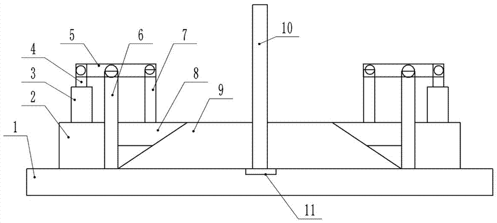
[0015] The reference signs in the drawings of the description include: base 1, fixed column 2, hydraulic cylinder 3, support rod 4, transmission rod 5, vertical rod 6, pressure rod 7, pressure block 8, fixture 9, workpiece 10, groove 11 .

[0016] The embodiment is basically as figure 1 Shown:

[0017] The hydraulic cylinder fixture of this embodiment includes a base 1, the center line of the base 1 is provided with a groove 11 for placing a workpiece 10; The chute is slidingly connected with two clamps 9 symmetrically arranged on the center line of the base 1. The side of the clamp 9 facing the fixed column 2 is an inclined surface at an angle of 45 degrees to the horizontal direction. The top of the fixed column 2 is provided with a hydraulic pressure Cylinder 3, the output end of the hydraulic cylinder 3 is provided with a support rod 4, and the side of the fixed co...


PUM


Abstract

The invention belongs to the field of hydraulic equipment, and particularly relates to a hydraulic cylinder clamp. The hydraulic cylinder clamp comprises a base; a groove used for containing a workpiece is formed in the center line of the base; fixing columns are fixed to the two sides of the base; a sliding groove located between the fixing columns is formed in the base and is in sliding connection with two clamp bodies symmetrical with respect to the center line of the base; the side, facing the corresponding fixing column, of each clamp body is a slope forming an 45-degree included angle with the horizontal direction; a hydraulic cylinder is arranged on the top of each fixing column; a support rod is arranged at the output end of each hydraulic cylinder; a stand rod fixed to the base is arranged on the side, close to the center line of the base, of each fixing column; a transmission rod is hinged to the top of each stand rod; one end of each transmission rod is hinged to the corresponding support rod; a pressure rod is hinged to the other end of each transmission rod; a pressure block of a wedge-shaped structure is fixedly connected with the bottom of each pressure rod; the side, away from the corresponding fixing column, of each pressure block is parallel with the slope of the corresponding clamp body; and the slopes of the clamp bodies are frosted surfaces. The hydraulic cylinder clamp can be prevented from shifting due to inconsistent stress, so that the machining quality is ensured.

Description

technical field [0001] The invention belongs to the field of hydraulic equipment, and in particular relates to a hydraulic cylinder clamp. Background technique [0002] In the machinery industry, the hydraulic cylinder is an important part of power transmission. It is a device that converts hydraulic energy into mechanical energy and enables the machine to achieve reciprocating linear motion or swing. Its transmission works smoothly and has high reliability. The hydraulic cylinder is located The working environment is harsh, especially in the metallurgy, mining and shipping industries, which have high requirements for the operation of machinery and equipment. During the mechanical transmission process, the hydraulic cylinder is in a harsh working environment of high pressure, impact and instability. In the control of industrial production In the process, a large number of hydraulic cylinders are used. For example, when workpieces are processed on machine tools, fixture posi...

Claims


Application Information

Patent Timeline
Patent Type & Authority Applications(China)
IPC IPC(8): B23Q3/08
CPCB23Q3/082
Inventor 谷山品
Owner CHONGQING WEIQING HYDRAULIC MACHINERY CO LTD
Why Eureka
Try Eureka