Condenser pipe arrangement spot welding machine with hanging rack

A technology of condensing tubes and hanging racks, which is applied in the field of condensing tube discharge spot welding machines, which can solve the problems of large fluctuations in product quality, inconvenient operation, and slow processing speed, and achieve uniform spot welding effects, convenient fixed connections, and fast connection speeds Effect

Active Publication Date: 2017-12-22
CHANGZHOU CHANGFA REFRIGERATION TECH CO LTD
View PDF6 Cites 3 Cited by
  • Summary
  • Abstract
  • Description
  • Claims
  • Application Information

AI Technical Summary

Problems solved by technology

[0003] The common welding method of wire tube condenser adopts manual operation method, manually arranges the condenser pipes, manually arranges the steel wires on the condenser pipes, and manually completes the whole row welding of the arranged steel wires. Production method, low production efficiency, many people, large fluctuations in product quality after welding, inaccurate positioning during welding, uneven thickness of solder joints, easy slipping or displacement of the steel wire placed on the condenser tube, inconvenient operation, and manual The welding operation is unstable, it is easy to make mistakes, and it is easy to cause people to be injured by the welding part. The manual operation method is not easy to fix the welding position. Manually put the steel wire on the condenser tube, and then perform welding. In this way, the position of the welding steel wire is easy to slip , low processing accuracy, uneven welding, poor connection effect, slow processing speed, low efficiency, and poor safety

Method used


Image

  • Condenser pipe arrangement spot welding machine with hanging rack
  • Condenser pipe arrangement spot welding machine with hanging rack
  • Condenser pipe arrangement spot welding machine with hanging rack

Examples


Embodiment

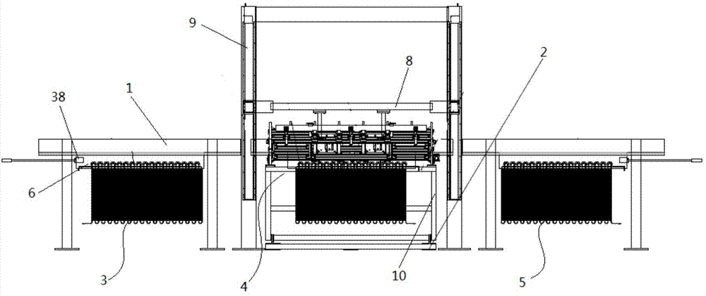
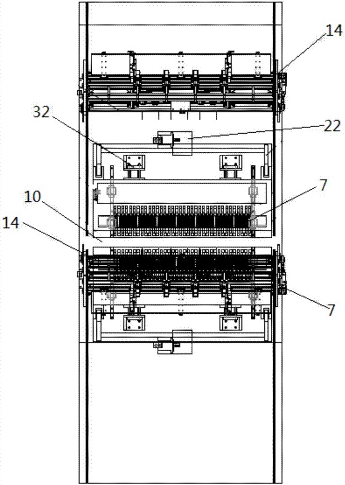
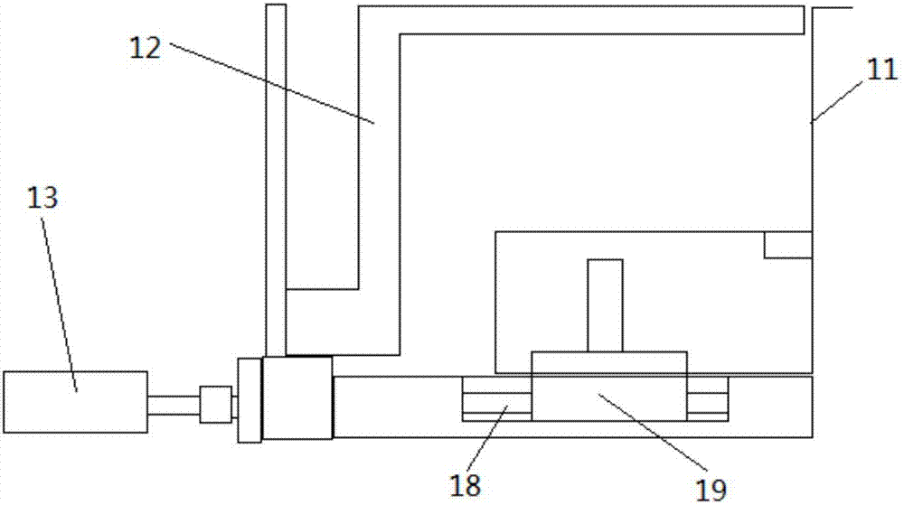
[0038] Such as Figure 1-7 As shown, this embodiment discloses a condensation tube discharge spot welder with a hanger, including a hanger mechanism 2 arranged on the X-axis track 1, and the mobile hanger mechanism 2 is sequentially moved in the direction of the X-axis track 1 A material hanging mechanism 3, a spot welding mechanism 4 and a blanking mechanism 5 are provided; the material hanging mechanism 3 includes a hanger 6; the spot welding mechanism 4 is provided with a spot welding device 7 on both sides of the X-axis track 1, and above the spot welding mechanism 4 A Y-axis lifting device 8 is provided along the Y-axis direction. The Y-axis lifting device 8 can move along the Y-axis track 9. The Y-axis lifting device 8 can be automatically connected with the hanger 6 that moves below. Welding clamping station 10; Hanger 6 can move in the spot welding clamping station 10, and spot welding clamping station 10 is evenly provided with several U-shaped draw-in grooves 11, and...


PUM


Abstract

The invention discloses a condenser pipe arrangement spot welding machine with a hanging rack. The condenser pipe arrangement spot welding machine comprises a hanging rack structure arranged on an X-axis track. A material hanging mechanism, a spot welding mechanism and a discharging mechanism are sequentially arranged on the movable hanging rack mechanism in the direction of the X-axis track. The material hanging mechanism comprises the hanging rack. Spot welding devices are correspondingly arranged on the spot welding mechanism along the two sides of the X-axis track. A Y-axis lifting device is arranged on the upper portion of the spot welding mechanism in the Y-axis direction. The Y-axis lifting device can move along a Y-axis track. The Y-axis lifting device can be automatically connected with the hanging rack moving to the portion below the Y-axis lifting device. A spot welding clamping station is arranged below the Y-axis lifting device. The hanging rack can move into the spot welding clamping station. Multiple U-shaped clamping grooves are uniformly formed in the spot welding clamping station. Multiple L-shaped steel wire limiting pieces are arranged on one sides of the U-shaped clamping grooves. A push air cylinder is connected to each steel wire limiting piece. Discharging machines are arranged on the two sides of the spot welding mechanism.

Description

technical field [0001] The invention relates to the field of spot welding machines, in particular to a condensation pipe discharging spot welding machine with a hanger Background technique [0002] The silk tube condenser is generally designed as a hollow tube, and then the long condenser is convolutedly bent into a multiple S-shaped structure. Steel wires are welded on the bent multiple S-shaped tubular structures, and the welding quality of the steel wires directly affects the heat dissipation effect of the wire tube condenser. [0003] The common welding method of wire tube condenser adopts manual operation method, manually arranges the condenser pipes, manually arranges the steel wires on the condenser pipes, and manually completes the whole row welding of the arranged steel wires. Production method, low production efficiency, many people, large fluctuations in product quality after welding, inaccurate positioning during welding, uneven thickness of solder joints, easy ...

Claims


Application Information

Patent Timeline
Patent Type & Authority Applications(China)
IPC IPC(8): B23K11/11B23K11/36B23K37/04
CPCB23K11/11B23K11/36B23K37/04B23K37/0443
Inventor 顾柳青姚晓强丁伟平
Owner CHANGZHOU CHANGFA REFRIGERATION TECH CO LTD
Why Eureka
Try Eureka