Al technical title is built by PatSnap Al team. It summarizes the technical point description of the patent document.
An equipment and plate technology, applied in the field of plate conveying equipment, can solve the problems of not being able to cooperate well with the edge banding machine, the quality of the plate is not up to standard, and the edge banding effect is poor, so as to achieve material cost saving, good rolling effect, good adaptability
Pending Publication Date: 2018-01-19
浙江云峰莫干山家居用品有限公司
View PDF9 Cites 0 Cited by
Summary
Abstract
Description
Claims
Application Information
AI Technical Summary
This helps you quickly interpret patents by identifying the three key elements:
Problems solved by technology
Method used
Benefits of technology
Problems solved by technology
[0002] At present, in the home furnishing industry, after the sawing of the board is completed, for subsequent use, an edge banding machine is usually used to seal the sawn board. The current edge banding process is highly mechanized. In order to improve the edge banding Efficiency requires the use of conveying equipment to continuously send the boards that need to be edge-banded to the edge-banding machine. The existing conveying equipment that sends the boards to the edge-banding machine usually simply uses a motor to drive the gear to drive the conveyor belt to rotate. The plate is rotated to be sent to the edge banding machine for edge banding. No matter what width the plate is, the same conveying equipment is used uniformly, which has poor adaptability. When it is necessary to transport the plate with a larger or smaller width, it cannot The specific width of the board is adjusted accordingly, which cannot better cooperate with the edge banding work of the edge banding machine, resulting in poor edge banding effect, and the quality of the board after edge banding is prone to be substandard
Method used
Image
Click on the blue label to locate the original text in one second.
Reading with bidirectional positioning of images and text.
Examples
Embodiment Construction
[0022] The present invention will be further described below in conjunction with the accompanying drawings and embodiments, but not as a basis for limiting the present invention.
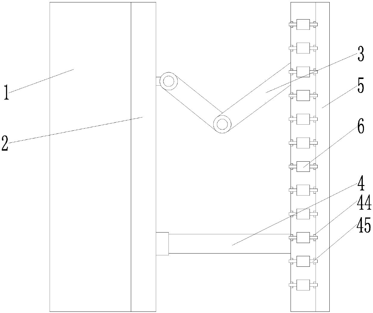
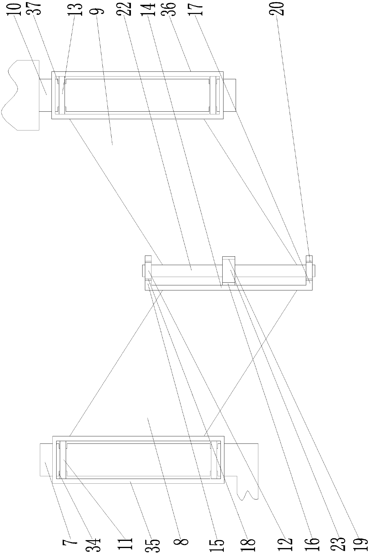
[0023] like figure 1 The shown equipment for plate conveying includes support 1, conveyor belt 2, such as figure 2 The first telescoping mechanism 3 shown, as Figure 4In the second telescopic mechanism 4 and auxiliary guide rail 5 shown, the conveyer belt is arranged in the middle part of one side of the support, the first telescopic mechanism and the second telescopic mechanism are all fixed on the bottom of one side of the frame, and the auxiliary guide rail passes through the first telescopic mechanism and the second telescopic mechanism. The second telescopic mechanism is arranged on the outside of the frame, and the auxiliary guide rail is arranged in parallel with the conveyor belt, and several rollers 6 are installed on the auxiliary guide rail; the first telescopic mechanism includes a fi...
PUM
Abstract
The invention relates to the technical field of panel conveying equipment, and particularly discloses equipment for panel conveying. The equipment comprises a support, a conveying belt, a first telescopic mechanism, a second telescopic mechanism, an auxiliary guide rail, a first fixing rod, a first rotation arm, a second rotation arm, a second fixing rod, an upper fixing part, a middle fixing part, a lower fixing part, an upper fixing hole, a middle fixing hole and a lower fixing hole. An arc pit is arranged in the middle fixing hole, the second rotation arm is provided with a rotation rod, the rotation rod is provided with a circular rotation block provided with an installing groove, the installing groove is internally provided with a first spring, and the first spring is provided with afirst positioning ball; the second telescopic mechanism comprises a sleeve, a telescopic rod and a third fixing rod, an arc limiting groove is formed in the sleeve, the telescopic rod is provided witha guiding groove, a second spring is arranged in the guiding spring, and the second spring is provided with a second positioning ball. The equipment has the beneficial effects that width is adjustable, adaptability is high, and the conveying efficiency is high.
Description
technical field [0001] The invention relates to the technical field of sheet material conveying equipment, in particular to a device for sheet material conveying. Background technique [0002] At present, in the home furnishing industry, after the sawing of the board is completed, for subsequent use, an edge banding machine is usually used to seal the sawn board. The current edge banding process is highly mechanized. In order to improve the edge banding Efficiency requires the use of conveying equipment to continuously send the boards that need to be edge-banded to the edge-banding machine. The existing conveying equipment that sends the boards to the edge-banding machine usually simply uses a motor to drive the gear to drive the conveyor belt to rotate. The plate is rotated to be sent to the edge banding machine for edge banding. No matter what width the plate is, the same conveying equipment is used uniformly, which has poor adaptability. When it is necessary to transport ...
Claims
Application Information
Patent Timeline
Application Date:The date an application was filed.
Publication Date:The date a patent or application was officially published.
First Publication Date:The earliest publication date of a patent with the same application number.
Issue Date:Publication date of the patent grant document.
PCT Entry Date:The Entry date of PCT National Phase.
Estimated Expiry Date:The statutory expiry date of a patent right according to the Patent Law, and it is the longest term of protection that the patent right can achieve without the termination of the patent right due to other reasons(Term extension factor has been taken into account ).
Invalid Date:Actual expiry date is based on effective date or publication date of legal transaction data of invalid patent.