switch

A technology of switches and bearings, which is applied in the direction of electric switches, mechanical control devices, instruments, etc., can solve the problems of time-consuming assembly, large number of parts and assembly processes, and low productivity, and achieve fewer parts and fewer production processes. Less and more productive effects

Active Publication Date: 2019-12-03
ORMON CORP
View PDF5 Cites 0 Cited by
  • Summary
  • Abstract
  • Description
  • Claims
  • Application Information

AI Technical Summary

Problems solved by technology

Therefore, the multi-directional switch assembly has the problems of a large number of parts and assembly steps, time-consuming assembly, and low productivity.

Method used


Image

  • switch
  • switch
  • switch

Examples


Embodiment Construction

[0103] Before continuing the description of the present invention, the same reference numerals are assigned to the same components in the drawings.

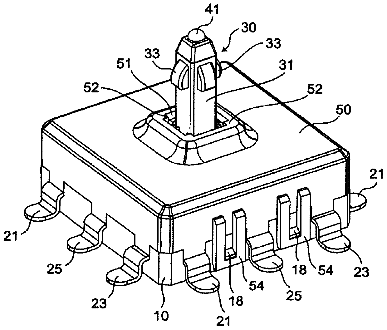
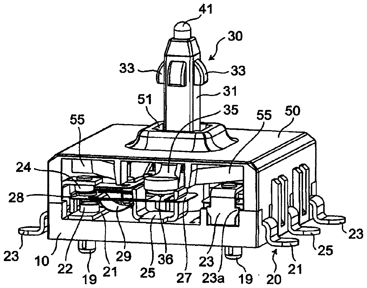
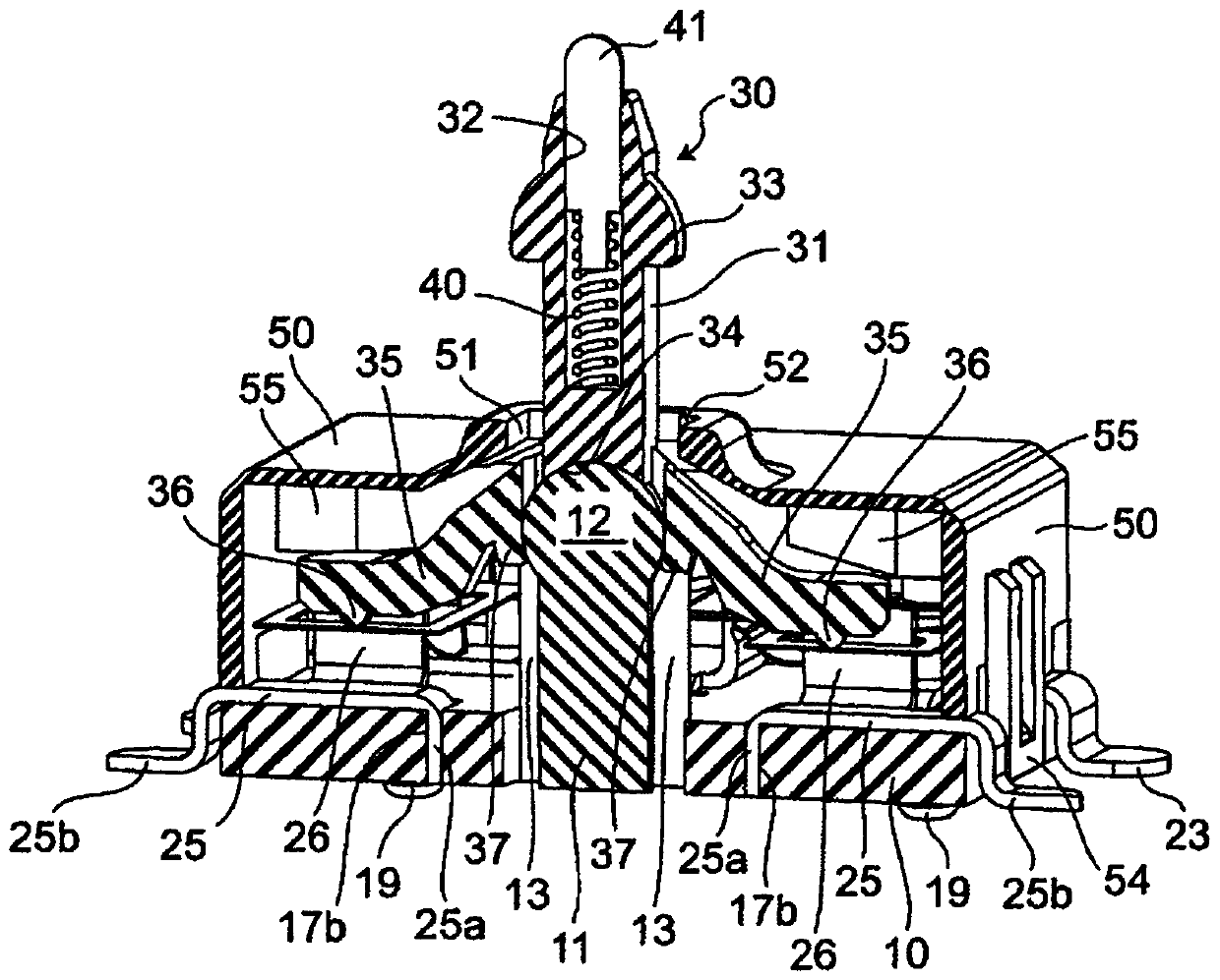
[0104] refer to Figure 1 to Figure 45 A switch according to an embodiment of the present invention will be described.

[0105] In addition, in the following description, terms indicating directions such as "upper", "lower", "left", "right" and other terms including these terms are used when describing the configuration shown in the drawings. These terms are used for easy understanding of the embodiments through the drawings. Therefore, these terms are not limited to the terms indicating the direction in which the embodiments of the present invention are actually used, and the technical scope claimed in the present invention should not be limitedly interpreted by these terms.

[0106] Such as Figure 1 to Figure 14 As shown, the switch of the first embodiment is, as an example, a switch operable in four directions.

[0107] T...


PUM


Abstract

The switch of the present invention has: a base (10) protrudingly provided with a bearing body (11) having a bearing portion (12) at the upper end; an operating shaft (31) with a lower end surface rotatably supported on the bearing portion; An operating lever (30) of at least one operating foot (35) extending toward the base; a movable contact (28) and a fixed contact (24) that can be moved by the operating foot when the operating shaft is rotated are arranged on The upper surface of the base and at least one contact mechanism (20) for opening and closing the movable contact relative to the fixed contact by operating the foot.

Description

technical field [0001] The present invention relates to switches, in particular switches capable of multi-directional operation. Background technique [0002] Conventionally, as a multi-directional switch, there are, for example, a multi-directional switch unit and a switch module (see Patent Document 1). Moreover, the multi-directional switch assembly and switch module such as Figure 46 As shown, the switch modules 101, 101' are driven by the actuator 102. [0003] Patent Document 1: Specification of US Patent No. 6787716 [0004] However, in the multi-directional switch assembly and switch module, the actuator 102 is centered on the guide pin 102c, and is assembled with an internal control part 102a and an external control part 102b by using a universal joint. Therefore, the multidirectional switch assembly has the problems of a large number of parts and assembly steps, time-consuming assembly, and low productivity. Contents of the invention [0005] In view of the a...

Claims


Application Information

Patent Timeline
Patent Type & Authority Patents(China)
IPC IPC(8): H01H25/04
CPCH01H21/24H01H25/04G05G2009/04707G05G9/047H01H21/12H01H21/22H01H21/36H01H2235/01
Inventor 篠原彰弥篠原贤二
Owner ORMON CORP
Why Eureka
Try Eureka