A thrust sliding bearing clearance and contact spot adjustment device and method

A technology of thrust sliding bearings and contact spots, which is applied in the direction of measuring devices, mechanical measuring devices, mechanical devices, etc., to achieve the effect of adjustment

Active Publication Date: 2019-06-07
CHONGQING GEARBOX
View PDF5 Cites 0 Cited by
  • Summary
  • Abstract
  • Description
  • Claims
  • Application Information

AI Technical Summary

Problems solved by technology

At present, there is no effective method to adjust the contact spots and axial clearance of thrust sliding bearings.

Method used


Image

  • A thrust sliding bearing clearance and contact spot adjustment device and method
  • A thrust sliding bearing clearance and contact spot adjustment device and method
  • A thrust sliding bearing clearance and contact spot adjustment device and method

Examples


Embodiment 1

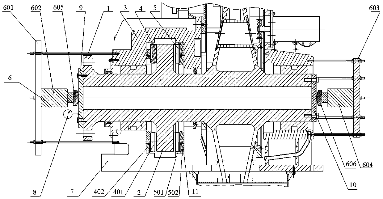
[0045] Such as figure 1 As shown, the present invention discloses a thrust sliding bearing clearance and contact spot adjustment device, which includes a thrust plate 2, a forward thrust device 4, a reverse thrust device 5, a driving device 6 and a measuring device 8.

[0046] Wherein, the thrust disc 2 is connected to the transmission shaft 1 around the transmission shaft 1. In order to increase the firmness of the connection between the thrust disc 2 and the transmission shaft 1, in this embodiment, the thrust disc 2 and the transmission shaft 1 have an integrated structure. The thrust sliding bearing 3 is installed on the transmission shaft 1, the thrust disk 2 is arranged in the inner space of the thrust sliding bearing 3, and the front side of the thrust disk 2 and the reverse side of the thrust disk 2 are provided with a colorant layer. It should be noted that, in this article, front, back, forward and reverse are just for naming convenience, and have no other meaning. ...

Embodiment 2

[0053] In the second embodiment provided by the present invention, the thrust sliding bearing clearance and contact spot adjustment device in this embodiment is similar in structure to the thrust sliding bearing clearance and contact spot adjustment device in Embodiment 1, and the similarities are not discussed. Again, just the differences.

[0054] In this embodiment, it is specifically disclosed that the thrust plate 2 is integrally connected with the transmission shaft 1 .

[0055] In this embodiment, the structures of the vehicle thrust device and the rollover thrust device are specifically disclosed. Wherein, the front vehicle thrust device 4 includes a front vehicle thrust block 401 and a front vehicle collar 402, the front vehicle collar 402 is installed on the first surface, the front vehicle thrust block 401 is installed in the front vehicle collar 402, and the reverse vehicle thrust device 5 includes The reverse thrust block 501 and the reverse collar 502, the rever...

Embodiment 3

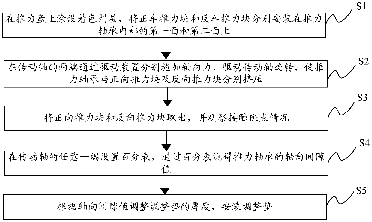
[0069] Such as figure 2 As shown, the present invention provides a thrust sliding bearing clearance and contact spot adjustment method, comprising the following steps:

[0070] Step S1: coating the colorant layer on the thrust plate 2, and installing the forward thrust block 401 and the reverse thrust block 501 on the first surface and the second surface of the thrust sliding bearing 3 respectively.

[0071]Specifically: the front and back of the thrust plate 2 are coated with a coloring agent layer, the front car thrust block 401 is packed into the front car collar 402, the reverse thrust block 501 is packed in the back car collar 502, and the front car collar 402 and the reverse collar 502 are installed on the first surface inside the thrust sliding bearing 3 and the second surface of the thrust sliding bearing 3 respectively.

[0072] Step S2: Apply axial force to both ends of the transmission shaft 1 through the driving device 6 to drive the transmission shaft 1 to rotat...


PUM


Abstract

The invention discloses a regulating device and method for the clearance and the contact spot of a thrust bearing. The regulating device comprises a thrust collar, an ahead thrust device, an astern thrust device, a driving device and a measuring device, wherein the thrust collar is arranged inside the thrust bearing; colorant layers are arranged on the front surface and the back surface of the thrust collar; the ahead thrust device is arranged on a first surface in the thrust bearing; the astern thrust device is arranged on a second surface in the thrust bearing; the driving device is used fordriving a transmission shaft to move axially; when the transmission shaft moves forwards, the ahead thrust device is pressed on the front surface of the thrust collar, and when the transmission shaftmoves backwards, the astern thrust device is pressed on the back surface of the thrust collar; and the measuring device is capable of measuring the axial clearance value of the thrust bearing. The axial clearance check and the contact spot check are realized by one device, so that the efficiency is improved, and through grinding, the size of an adjusting pad can be successfully adjusted, so thatthe accuracy is improved.

Description

technical field [0001] The invention relates to the technical field of bearings, in particular to a device and method for adjusting gaps and contact spots of thrust sliding bearings. Background technique [0002] As the key equipment of the power system, the marine gearbox can transmit the thrust generated by the propeller to the hull through the thrust sliding bearing of the gearbox, so that the ship can move forward or backward. Thrust sliding bearing, as a bearing that bears axial thrust and restricts the axial movement of the shaft, is an indispensable part in the structure of large marine gearboxes and is widely used. In order to ensure the force balance of the thrust sliding bearing and prevent bearing damage caused by the unbalanced load of the thrust structure of the gearbox, it is necessary to adjust the contact spots and axial clearance of the thrust sliding bearing to ensure the assembly accuracy and application performance of the thrust sliding bearing. At prese...

Claims


Application Information

Patent Timeline
Patent Type & Authority Patents(China)
IPC IPC(8): B23P19/027B23P19/10G01B5/14
CPCB23P19/027B23P19/10G01B5/146
Inventor 李强冯健方朝野叶辉曾昭勇封富顺赵晓航
Owner CHONGQING GEARBOX
Why Eureka
Try Eureka