Regulating device and method for clearance and contact spot of thrust bearing
A technology of thrust sliding bearings and contact spots, which is applied in the field of bearings to achieve the effect of adjustment
- Summary
- Abstract
- Description
- Claims
- Application Information
AI Technical Summary
Problems solved by technology
Method used
Image
Examples
Embodiment 1
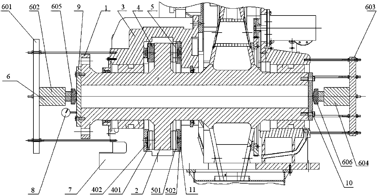
[0045] like figure 1 As shown, the present invention discloses a thrust sliding bearing clearance and contact spot adjustment device, which includes a thrust plate 2, a forward thrust device 4, a reverse thrust device 5, a driving device 6 and a measuring device 8.
[0046] Wherein, the thrust disc 2 is connected to the transmission shaft 1 around the transmission shaft 1. In order to increase the firmness of the connection between the thrust disc 2 and the transmission shaft 1, in this embodiment, the thrust disc 2 and the transmission shaft 1 have an integrated structure. The thrust sliding bearing 3 is installed on the transmission shaft 1, the thrust disk 2 is arranged in the inner space of the thrust sliding bearing 3, and the front side of the thrust disk 2 and the reverse side of the thrust disk 2 are provided with a colorant layer. It should be noted that, in this article, front, back, forward and reverse are just for naming convenience, and have no other meaning.
[...
Embodiment 2
[0053] In the second embodiment provided by the present invention, the thrust sliding bearing clearance and contact spot adjustment device in this embodiment is similar in structure to the thrust sliding bearing clearance and contact spot adjustment device in Embodiment 1, and the similarities are not discussed. Again, just the differences.
[0054] In this embodiment, it is specifically disclosed that the thrust plate 2 is integrally connected with the transmission shaft 1 .
[0055] In this embodiment, the structures of the vehicle thrust device and the rollover thrust device are specifically disclosed. Wherein, the front vehicle thrust device 4 includes a front vehicle thrust block 401 and a front vehicle collar 402, the front vehicle collar 402 is installed on the first surface, the front vehicle thrust block 401 is installed in the front vehicle collar 402, and the reverse vehicle thrust device 5 includes The reverse thrust block 501 and the reverse collar 502, the rever...
Embodiment 3
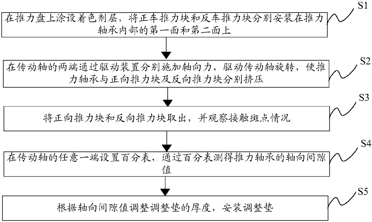
[0069] like figure 2 As shown, the present invention provides a thrust sliding bearing clearance and contact spot adjustment method, comprising the following steps:
[0070] Step S1: coating the colorant layer on the thrust plate 2, and installing the forward thrust block 401 and the reverse thrust block 501 on the first surface and the second surface of the thrust sliding bearing 3, respectively.
[0071]Specifically: the front and back of the thrust plate 2 are coated with a coloring agent layer, the front car thrust block 401 is packed into the front car collar 402, the reverse thrust block 501 is packed in the back car collar 502, and the front car collar 402 and the reverse collar 502 are installed on the first surface inside the thrust sliding bearing 3 and the second surface of the thrust sliding bearing 3 respectively.
[0072] Step S2: Apply axial force to both ends of the transmission shaft 1 through the driving device 6 to drive the transmission shaft 1 to rotate,...
PUM
 Abstract
Description
Claims
Application Information
 - R&D
- Intellectual Property
- Life Sciences
- Materials
- Tech Scout
- Unparalleled Data Quality
- Higher Quality Content
- 60% Fewer Hallucinations
Browse by: Latest US Patents, China's latest patents, Technical Efficacy Thesaurus, Application Domain, Technology Topic, Popular Technical Reports.
© 2025 PatSnap. All rights reserved.Legal|Privacy policy|Modern Slavery Act Transparency Statement|Sitemap|About US| Contact US: help@patsnap.com


