
Vortex compressor

A scroll compressor and compression chamber technology, applied in the field of compressors, can solve the problems of reducing the viscosity of lubricating oil, reducing the lubricating effect, reducing the energy efficiency of the compressor, etc. The effect of small frictional power consumption

Pending Publication Date: 2017-12-19
ZHUHAI GREE REFRIGERATION TECH CENT OF ENERGY SAVING & ENVIRONMENTAL PROTECTION
View PDF4 Cites 0 Cited by
  • Summary
  • Abstract
  • Description
  • Claims
  • Application Information

AI Technical Summary

Problems solved by technology

However, for scroll compressors with non-floating movable scrolls, during normal operation, the movable scrolls are pressed against the support surface of the upper bracket by the gas pressure in the compression chamber, and the movable scrolls are flattened around the center of the crankshaft with a fixed radius. During dynamic motion, friction will occur between the back of the movable scroll and the supporting surface of the upper bracket, and the friction will generate high temperature, which will reduce the viscosity of the lubricating oil, that is, reduce the lubricating effect
As time goes by, the contact surface between the movable scroll and the upper bracket will wear out, and the frictional power consumption at the contact surface will gradually increase, which may lead to a decrease in the energy efficiency of the compressor, or worse, with the wear and tear of the two Aggravated, causing damage to other components of the compressor, thus affecting the reliability of the compressor
[0003] In the prior art, in order to solve the problem of wear and tear between the movable scroll and the upper bracket of the scroll compressor, it is common practice to set up an oil groove on the bearing surface of the upper bracket to improve the lubricity between the movable scroll and the upper bracket, thereby reducing the wear, however, due to the high pressure between the movable scroll and the upper bracket, the friction power consumption between the two is still high

Method used


Image

  • Vortex compressor
  • Vortex compressor
  • Vortex compressor

Examples


Embodiment Construction

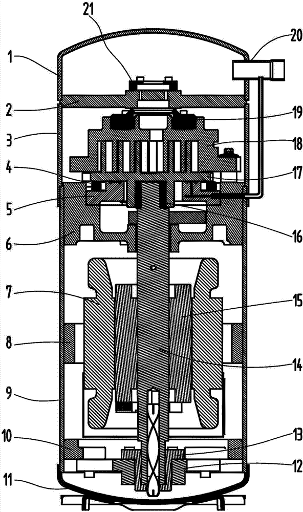
[0037] Before proceeding to describe the main features of the scroll compressor of the present invention in detail, first in conjunction with figure 1 The general characteristics of this scroll compressor will be described.

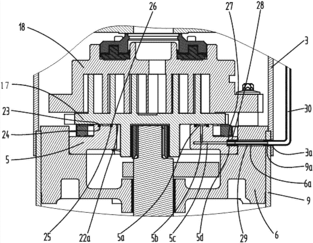
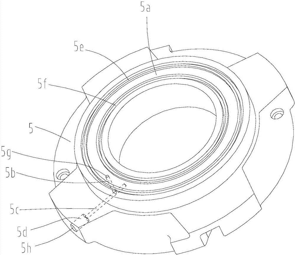
[0038] Such as figure 1 As shown, the scroll compressor mainly includes a motor 7, an upper bracket 6, a lower bracket 12, a fixed scroll 18, a movable scroll 17, an Oldham slip ring 4, a crankshaft 14, and the like. The motor 7 is fixed on the lower casing 9 through the motor fixing frame 8, and the upper bracket 6 is fixed on the lower casing 9 through an interference fit and an axial thrust structure. The movable scroll 17 and the fixed scroll 18 are opposed to each other with a phase angle difference of 180 degrees, and the movable scroll 17 is installed on the upper bracket 6 and supported by the support plate 5, and the support plate 5 is installed on the upper bracket 6, and passes through Screws are fixed on the upper bracket 6, and the upper br...


PUM


Abstract

The invention discloses a vortex compressor. The vortex compressor comprises a static vortex plate and a dynamic vortex plate, wherein the static vortex plate is meshed with the dynamic vortex plate to form a compression cavity; the rear surface of the dynamic vortex plate is supported on a dynamic vortex plate supporting component; a cross-shaped slide ring is arranged between the dynamic vortex plate and the dynamic vortex plate support component; a backpressure cavity is arranged on the radially-inner side of the cross-shaped slide ring between the dynamic vortex plate and the dynamic vortex plate support component; a pressure fluid is arranged in the backpressure cavity; and a pushing force is generated to the dynamic vortex plate by the pressure fluid, so that axial floating of the dynamic vortex plate is prevented. In the vortex compressor, the axial force generated by the fluid in the backpressure cavity can offset action force borne by the dynamic vortex plate from the static vortex plate and high pressure gas in the compression cavity, so that mutual action force between the dynamic vortex plate and the dynamic vortex plate support component can be lowered, and friction wear between the dynamic vortex plate and the dynamic vortex plate support component is reduced; friction power consumption is reduced; and reliability of the compressor is improved.

Description

technical field [0001] The invention relates to the technical field of compressors, in particular to a scroll compressor. Background technique [0002] The scroll compressor has the advantages of simple structure, small size, light weight, low noise, high mechanical efficiency and stable operation. However, for scroll compressors with non-floating movable scrolls, during normal operation, the movable scrolls are pressed against the support surface of the upper bracket by the gas pressure in the compression chamber, and the movable scrolls are flattened around the center of the crankshaft with a fixed radius. During dynamic motion, friction will be generated between the back of the movable scroll and the supporting surface of the upper bracket, and the friction will generate high temperature, which will reduce the viscosity of the lubricating oil, that is, reduce the lubricating effect. As time goes by, the contact surface between the movable scroll and the upper bracket wil...

Claims


Application Information

Patent Timeline
Patent Type & Authority Applications(China)
IPC IPC(8): F04C18/02F04C29/00
CPCF04C18/0215F04C29/0021
Inventor 李海港郭求和曹贞文李立民余世顺
Owner ZHUHAI GREE REFRIGERATION TECH CENT OF ENERGY SAVING & ENVIRONMENTAL PROTECTION
Learn More