Camera monitoring device, and combined camera monitoring device

A monitoring device and combined technology, which is applied in the direction of image communication, TV, color TV parts, etc., can solve the problems of inconvenient vehicle-mounted camera products, poor adaptability of equipment application, and great difficulty, so as to improve versatility and composability High performance, strong adaptability to application scenarios, and fast fault location

Pending Publication Date: 2018-03-30
深圳市锐驰曼科技发展有限公司
View PDF9 Cites 0 Cited by
  • Summary
  • Abstract
  • Description
  • Claims
  • Application Information

AI Technical Summary

Problems solved by technology

The product volume is relatively large, the installation space and wiring construction time are long, difficult, poor reliability, high cost, complex disassembly and maintenance
If a failure occurs in a certain part, the product needs to be dismantled and repaired, and it needs to be reinstalled after the repair, which virtually increases the consumption of time and workload.
[0003] At present, the existing camera monitoring devices adopt a one-to-one design idea of ​​equipment and application scenarios. A kind of equipment can only be used in a single environment, and the application adaptability of the equipment is poor.
For example, the current on-board camera monitoring devices are divided into logistics vehicles, passenger cars, minivans, private cars, etc. Different types of vehicles have large differences in shape and many types. Logistics vehicles and passenger car products cannot be installed on small private cars. Camera products are inconvenient to use in home monitoring and other issues, so there are a wide variety of products and a price difference in versatility, which increases the cost of products to a certain extent

Method used


Image

  • Camera monitoring device, and combined camera monitoring device
  • Camera monitoring device, and combined camera monitoring device
  • Camera monitoring device, and combined camera monitoring device

Examples


Embodiment Construction

[0037] It should be noted that, in the case of no conflict, the embodiments in the present application and the features in the embodiments can be combined with each other.

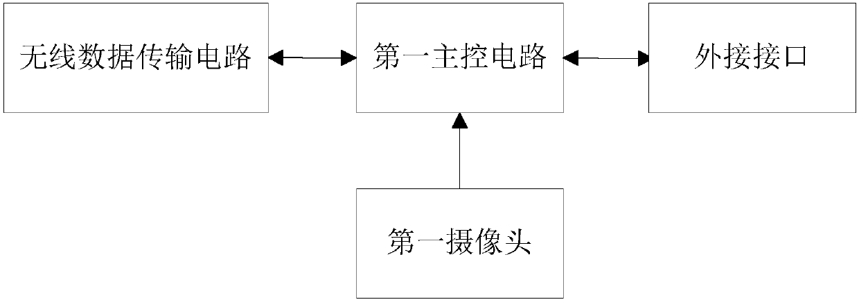
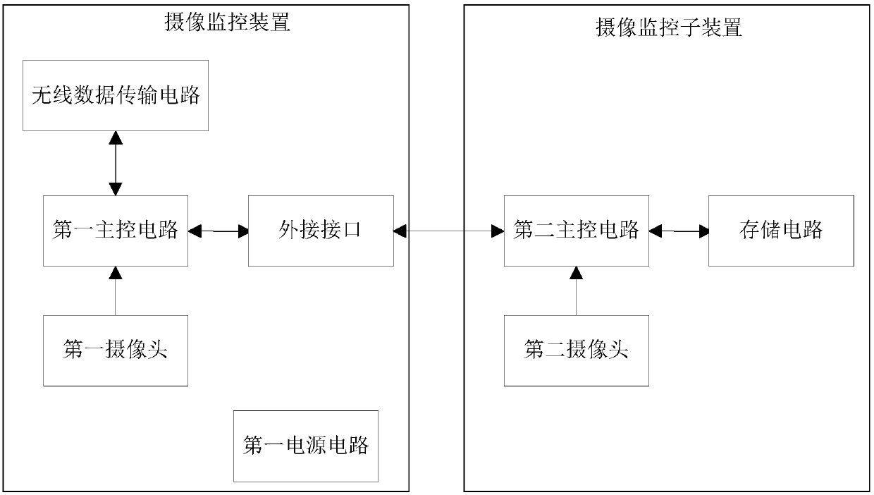
[0038] A camera monitoring device, refer to figure 1 , figure 1 It is a structural block diagram of an embodiment of the camera monitoring device of the present invention; it includes a first main control circuit, a first camera, a wireless data transmission circuit, an external interface for connecting the camera device and a first power supply circuit, and the first main control circuit is respectively It is connected with the wireless data transmission circuit and the external interface, the output end of the first camera is connected with the input end of the first main control circuit, and the first power supply circuit provides power for each circuit of the camera monitoring device. The camera monitoring device in the present invention is provided with an external interface for connecting the camera...


PUM


Abstract

The invention discloses a camera monitoring device comprising a first main control circuit, a first camera, a wireless data transmission circuit, an external interface used for connecting a camera device and a first power circuit. The invention also provides a combined camera monitoring device comprising a camera monitoring sub-device and the camera monitoring device. The camera monitoring deviceprovided by the invention is provided with the external interface used for connecting the camera device of external equipment, so that composability of the camera monitoring device is improved, and the problem of one-to-one application of traditional camera monitoring equipment is solved. In addition, the combined camera monitoring device uses the external interface to achieve combination and connection of the camera monitoring sub-device and the camera monitoring device, and the combined camera monitoring device can be used in a combined manner, and can also work independently, so that maintenance is facilitated, a fault position can be quickly positioned via changing the module, installation is facilitated, and versatility and composability of the camera monitoring device are improved.

Description

technical field [0001] The invention relates to the monitoring field, in particular to a camera monitoring device and a combined camera monitoring device. Background technique [0002] With the development of the security monitoring industry, vehicle monitoring and home monitoring have become two important segments of the security industry. The products for these two fields of application also vary. There are two general methods of monitoring products in the vehicle field: one is that the monitoring host cooperates with an external independent camera to realize the monitoring function. The camera is responsible for data collection, and the monitoring host is responsible for analyzing, storing and processing the collected data. A single camera or host cannot complete the monitoring application. This kind of product is generally used on the cart installed afterward; another way is to combine the audio and video The acquisition part and the processing part are taken as a whol...

Claims


Application Information

Patent Timeline
Patent Type & Authority Applications(China)
IPC IPC(8): H04N5/225H04N7/18
CPCH04N7/18H04N23/50
Inventor 王伟王强
Owner 深圳市锐驰曼科技发展有限公司
Why Eureka
Try Eureka