Electronic package and method of manufacture

A technology for electronic packages and electronic components, applied in the direction of electrical components, electric solid devices, circuits, etc., can solve problems such as abnormal electrical operation of the semiconductor package 1 and affect the electrical performance of the semiconductor package 1, so as to avoid Effects on Electrical Performance Affected

Active Publication Date: 2018-04-24
SILICONWARE PRECISION IND CO LTD
View PDF6 Cites 2 Cited by
  • Summary
  • Abstract
  • Description
  • Claims
  • Application Information

AI Technical Summary

Problems solved by technology

[0009] However, the existing semiconductor package 1 does not have a shielding structure for preventing Electromagnetic interference (EMI) during operation, so the semiconductor element 11 is susceptible to external electromagnetic interference (EMI). , causing the electrical function of the semiconductor package 1 to be abnormal, thus affecting the overall electrical performance of the semiconductor package 1

Method used


Image

  • Electronic package and method of manufacture
  • Electronic package and method of manufacture
  • Electronic package and method of manufacture

Examples


Embodiment Construction

[0059] Embodiments of the present invention are described below through specific examples, and those skilled in the art can easily understand other advantages and effects of the present invention from the content disclosed in this specification.

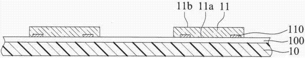
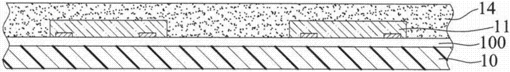
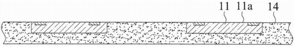
[0060] It should be noted that the structures, proportions, sizes, etc. shown in the drawings attached to this specification are only used to match the content disclosed in the specification for the understanding and reading of those skilled in the art, and are not intended to limit the implementation of the present invention. Limiting conditions, so there is no technical substantive meaning, any modification of structure, change of proportional relationship or adjustment of size, without affecting the effect and purpose of the present invention, should still fall within the scope of the present invention. The disclosed technical content must be within the scope covered. At the same time, terms such as "above", "first", "second" and ...


PUM


Abstract

Provided is an electronic package comprising a carrier structure, an electronic element and a shielding member disposed on the carrier structure, an encapsulating layer formed on the carrier structurefor encapsulating the electronic element and the shielding member, a metallic layer formed on the encapsulating layer and electrically connected to the shielding member, and an alignment member disposed at a side of the encapsulating layer, thereby allowing the periphery of the electronic element to be covered by the shielding member and the metallic layer to avoid external electromagnetic interference.

Description

technical field [0001] The invention relates to a packaging technology, in particular to a semiconductor package and its manufacturing method. Background technique [0002] With the vigorous development of the electronic industry, electronic products are gradually moving towards the trend of multi-function and high performance. In order to meet the packaging requirements of electronic package miniaturization (miniaturization), the technology of wafer level packaging (Wafer Level Packaging, referred to as WLP) has been developed. [0003] Figure 1A to Figure 1E It is a schematic cross-sectional view of the manufacturing method of the conventional wafer-level semiconductor package 1 . [0004] Such as Figure 1A As shown, a thermal release tape (thermal release tape) 100 is formed on a carrier 10; then, a plurality of semiconductor elements 11 are placed on the thermal release adhesive layer 100, and these semiconductor elements 11 have The opposite active surface 11 a and...

Claims


Application Information

Patent Timeline
Patent Type & Authority Applications(China)
IPC IPC(8): H01L23/552
CPCH01L23/552H01L2924/3025H01L2224/16227H01L2224/48227H01L2924/15311H01L2924/1815H01L2224/04105H01L2224/12105
Inventor 陈彦亨江政嘉
Owner SILICONWARE PRECISION IND CO LTD
Why Eureka
Try Eureka