Waste steel apron conveyor, conveying method and application

A technology of conveyors and scale plates, which is applied in the field of conveying methods and applications, scrap steel scale plate conveyors, can solve the problems of uneven tension force of the traction chain, reduce the service life of equipment, increase the cost of use, etc., and achieve the benefit of conveying , prolong the service life and reduce the production cost

Pending Publication Date: 2018-05-08
YIDU ZHONGQI HEAVY IND MASCH CO LTD
View PDF10 Cites 9 Cited by
  • Summary
  • Abstract
  • Description
  • Claims
  • Application Information

AI Technical Summary

Problems solved by technology

The current scale conveyor has the following problems: 1) The scale is a whole structure, and heavy materials (such as scrap steel, which weighs about several tons at a time) are directly thrown from the air to the scale, causing serious deformation of the scale. The damage is serious, which aggravates the wear of guide rails and conveying parts, increases the power consumption of the equipment, and increases the cost of use; 2). The traditional scale conveyor generally adopts a screw mechanism or other structures for buffer tension. The scale plate and the frame will be subjected to strong impact force from the material, and the generally installed buffer tensioning device cannot be adjusted by itself, which not only causes the teeth of the traction chain to fall off and skip teeth, but also makes the tension of the traction chain uneven and prone to breakage; 3 ), the existing conveying parts support the whole process using a single guide rail, due to sliding friction during operation, the wear of the guide rail and conveying parts is aggravated, the service life of the equipment is reduced, and noise pollution is increased

Method used


Image

  • Waste steel apron conveyor, conveying method and application
  • Waste steel apron conveyor, conveying method and application
  • Waste steel apron conveyor, conveying method and application

Examples


Embodiment Construction

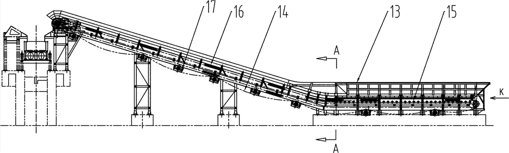
[0037] Such as figure 1 As shown, a scrap steel slab conveyor includes a frame 13, on which a slat group 14 for scrap steel transportation is provided. The slat group 14 is along a horizontal support mechanism 15, an inclined support mechanism 16 and a return support mechanism 17 Cycle movement. The scrap steel slab conveyor is composed of a horizontal section, a curved section and an inclined section.

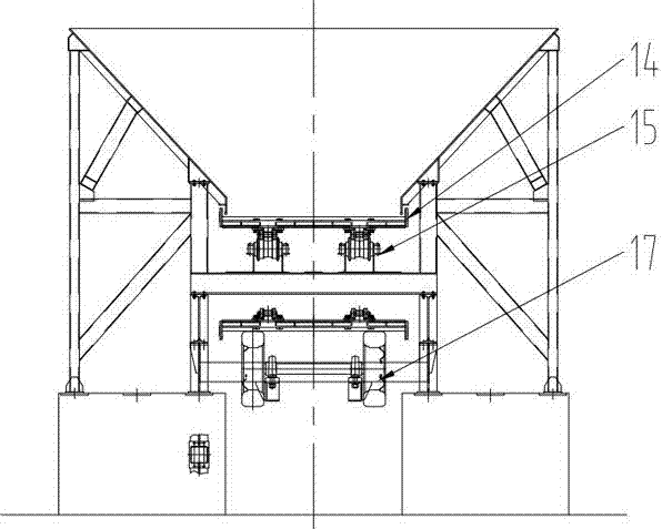
[0038] Such as Figure 3-4 As shown, the horizontal support mechanism 15 uses equidistant excavator support wheels, the inclined support mechanism 16 uses wear-resistant slide rails, and the return support mechanism 17 uses elastic runners 21 arranged at intervals, and the elastic runners 21 are transported along the return journey. The slat groups 14 are arranged up and down in the length direction. Through the use of excavator rollers at the receiving part, when the magnetic chuck is directly fed, the receiving end can buffer the impact of the feeding, and the bearing capacity...


PUM


Abstract

The invention provides a waste steel apron conveyor, a conveying method and application. The waste steel apron conveyor comprises a rack, an apron set for conveying of waste steel is arranged on the rack, circularly moves along a horizontal supporting mechanism, an oblique supporting mechanism and a return stroke supporting mechanism and comprises aprons and a conveying chain. The aprons comprisesquare tubes, upper channel plates and lower channel plates, the multiple square tubes are distributed on the upper channel plates, and the upper channel plates and the lower channel plates are mutually bent and buckled to form hollow stress frames. The conveying chain comprises two side plates, connecting circular tubes are welded to the front end of the position between the two side plates, pinshafts are mounted at the rear end of the position between the two side plates, and adjacent single-section chain bodies are connected into a whole by means of the method that the pin shafts are sleeved with the connecting circular pipes. Anchorage plates are mounted on the two side plates in a left-right symmetry mode, and the conveying chain is connected with the lower channel plates through theanchorage plates. According to the waste steel apron conveyor, through arrangement of the reinforced apron set, the overall conveying performance of the waste steel apron conveyor is improved.

Description

Technical field [0001] The invention relates to a slab conveyor, in particular to a scrap steel slab conveyor, a conveying method and application. Background technique [0002] Scrap steel needs to be fed continuously and evenly during the process of returning to the furnace or crushing, so it needs to be applied to the scale conveyor. The current slat conveyors have the following problems: 1) The slats are of a whole slab structure, and heavy materials (such as scrap steel, weighing several tons at a time) are thrown directly from the air to the slats, causing serious deformation of the slats. The damage is serious, which intensifies the wear of the guide rails and conveying parts, increases the power consumption of the equipment, and increases the cost of use; 2) The traditional slat conveyor buffer and tension generally adopt a screw mechanism or other structure. Due to the large blanking height, The slats and frame will be subject to the strong impact force of the material, ...

Claims


Application Information

Patent Timeline
Patent Type & Authority Applications(China)
IPC IPC(8): B65G17/06B65G23/44
CPCB65G17/065B65G23/44
Inventor 谭宏伟黄文静王海涛吴华峰
Owner YIDU ZHONGQI HEAVY IND MASCH CO LTD
Why Eureka
Try Eureka