Diffusion plate and direct type backlight module

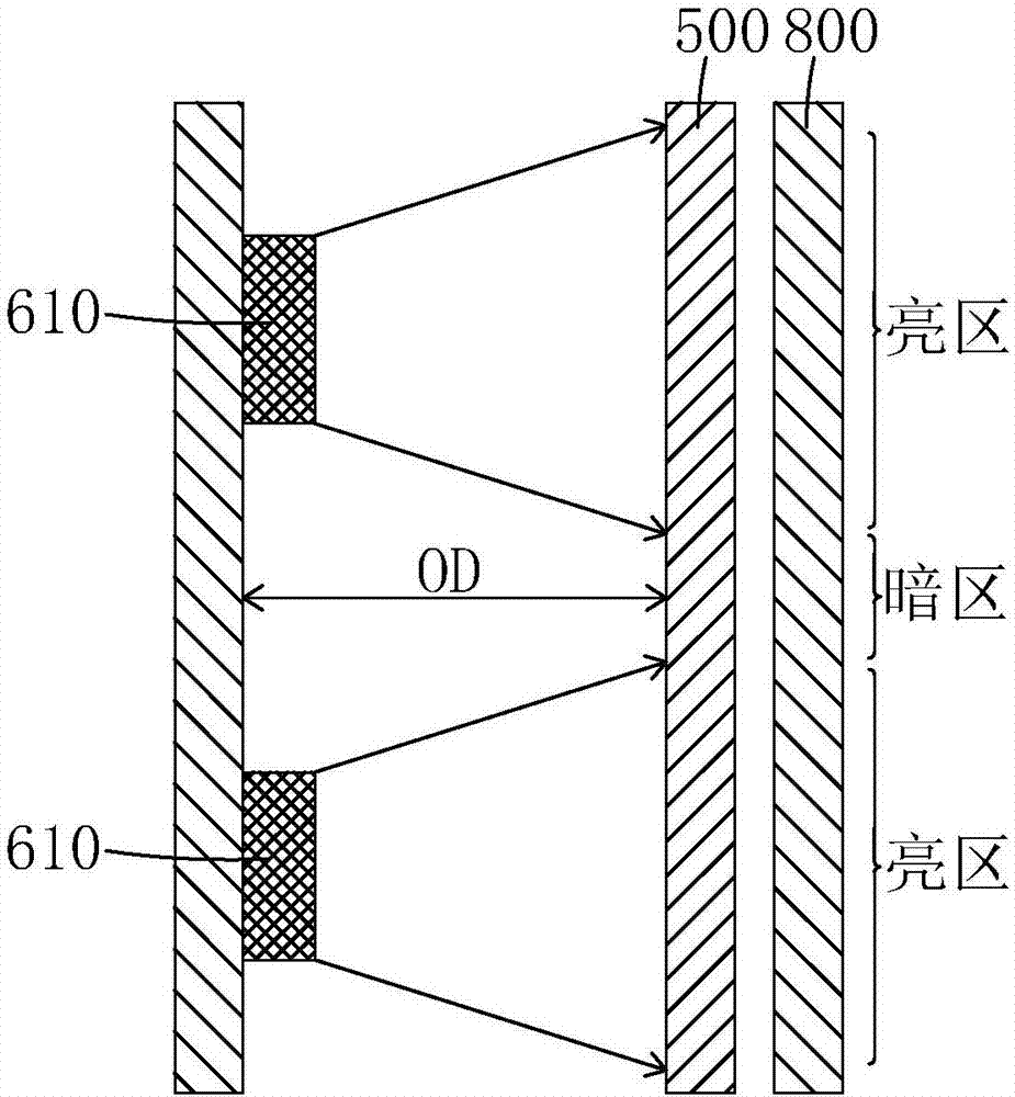
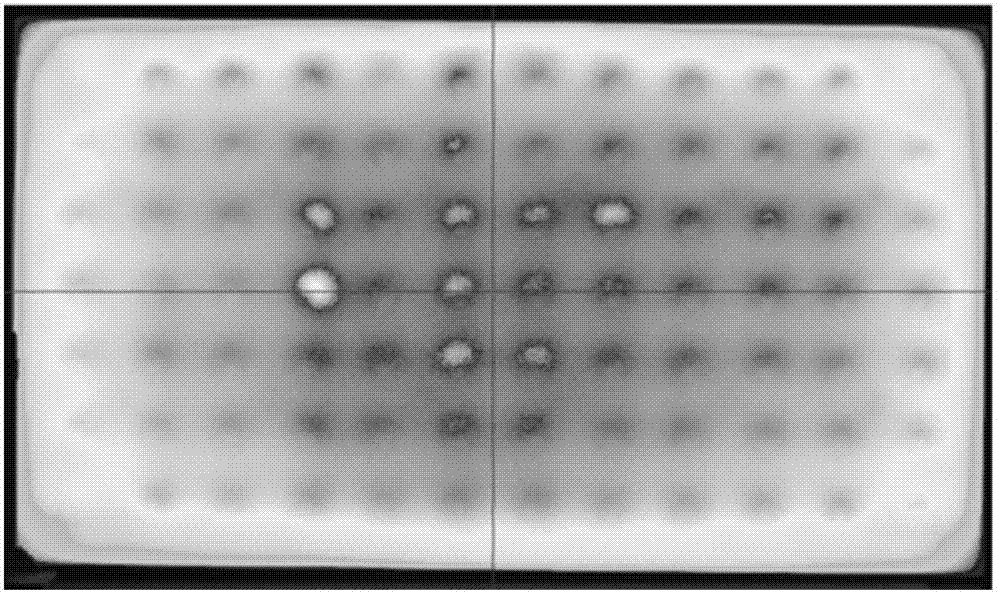
A technology of backlight module and diffusion plate, which is applied in the direction of optics, optical components, nonlinear optics, etc., can solve the problems of affecting TV appearance, adding LED lights 610, and uneven brightness and darkness, achieving excellent diffusion effect and realizing backlight brightness , Improve the effect of divergence angle

Inactive Publication Date: 2018-05-08
HUIZHOU CHINA STAR OPTOELECTRONICS TECHNOLOGY CO LTD
View PDF5 Cites 7 Cited by
  • Summary
  • Abstract
  • Description
  • Claims
  • Application Information

AI Technical Summary

Problems solved by technology

like figure 1 As shown, the principle of the light shadow problem is: due to the limited light-emitting angle of the LED lights 610, the non-light-emitting dark areas between adjacent LED lights 610 and the light-emitting areas of the nearby LED lights 610 form a picture with uneven brightness and darkness. Behind the diffuser plate 500 and the optical film 800, although the diffuser plate 500 and the optical film 800 have a certain diffusion effect on the light, it is not enough to change the problem of uneven brightness and darkness, and the lamp shadow problem arises from this
The current solution to the problem of light shadows is to reduce the LED spacing or increase the OD value. Both methods have disadvantages. The first method needs to increase the number of LED lights 610, thereby increasing the cost of the backlight module. The second method It is not conducive to the realization of ultra-thin design and affects the appearance of TV. Therefore, the industry urgently needs a method to solve the problem of light shadow without increasing the number of LED lights 610 and without increasing the OD value, so as to realize the low cost of direct-type backlight modules and ultra-thin design, and then realize the thin and light design of the TV set

Method used


Image

  • Diffusion plate and direct type backlight module
  • Diffusion plate and direct type backlight module
  • Diffusion plate and direct type backlight module

Examples


Embodiment Construction

[0046] In order to further illustrate the technical means adopted by the present invention and its effects, the following describes in detail in conjunction with preferred embodiments of the present invention and accompanying drawings.

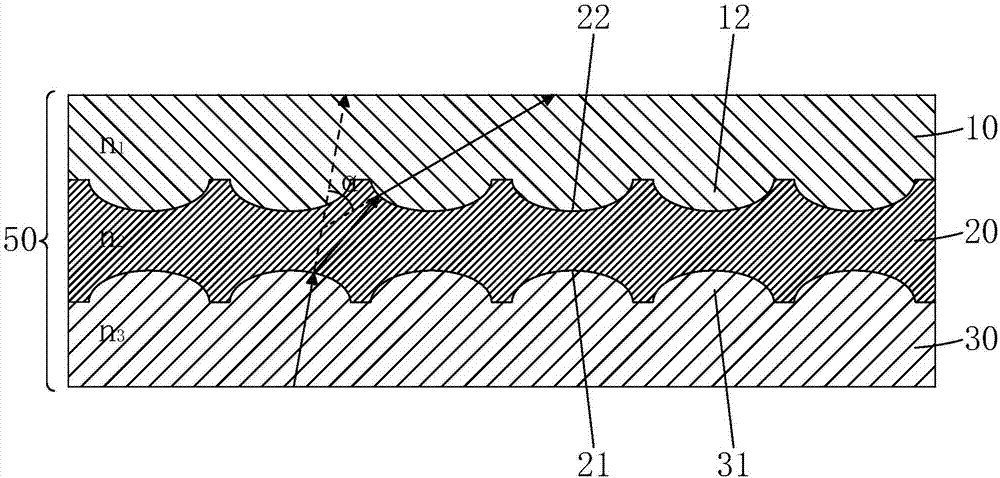
[0047] see Figure 3 to Figure 5C , is the first embodiment of the diffuser plate 50 of the present invention, and the diffuser plate 50 includes a first structural layer 10, a second structural layer 20, and a third structural layer 30 arranged in sequence from top to bottom; the third structure The side of the layer 30 away from the second structural layer 20 is the light incident side;

[0048] Define the refractive index n of the first structural layer 10 1 , the refractive index of the second structural layer 20 is n 2 , the refractive index of the third structural layer 30 is n 3 , then n 1 2 3 ;

[0049] The contact surfaces of the first structural layer 10 and the second structural layer 20 are tightly bonded; the contact surfaces...


PUM


Abstract

The invention provides a diffusion plate and a direct type backlight module. The diffusion plate is provided with a first groove at a light incoming side of a second structure layer and a second groove or a third protruding portion at a light outgoing side of the second structure layer and sets a first structure layer, the second structure layer and a third structure layer to be sequentially increased in reflective index, thereby being capable of significantly improving a divergence angle of incident light, and achieving the uniformity of backlight brightness. The direct type backlight modulecontains the diffusion plate. The diffusion plate has excellent diffusion effect for the light, so that a problem of lamp shadow can be solved while the number of LED lamps and the light mixing distance are reduced, thereby realizing low cost and ultrathin design of the direct type backlight module, and being conductive to achieving the application of the direct type backlight module in the fieldof ultrathin TVs.

Description

technical field [0001] The invention relates to the field of display technology, in particular to a diffuser plate and a direct-lit backlight module. Background technique [0002] Liquid crystal display (Liquid Crystal Display, LCD) has many advantages such as thin body, power saving, and no radiation, and has been widely used, such as: mobile phones, personal digital assistants (PDA), digital cameras, computer screens and notebook computers screen etc. [0003] Most of the liquid crystal display devices currently on the market are backlight liquid crystal display devices, which include a housing, a liquid crystal panel disposed in the housing, and a backlight module disposed in the housing. The structure of a traditional liquid crystal panel is composed of a color filter substrate (Color Filter), a thin film transistor array substrate (Thin Film TransistorArray Substrate, TFT Array Substrate), and a liquid crystal layer (Liquid Crystal Layer) arranged between the two subst...

Claims


Application Information

Patent Timeline
Patent Type & Authority Applications(China)
IPC IPC(8): G02B5/02G02F1/13357
CPCG02F1/133606G02B5/0236G02B5/0278G02F1/133603G02F1/133611G02F1/133607G02F1/133605H01L25/0753H01L33/60
Inventor 付琳琳何小宇
Owner HUIZHOU CHINA STAR OPTOELECTRONICS TECHNOLOGY CO LTD
Why Eureka
Try Eureka