SAR imaging method

An imaging method and azimuth technology, applied in the field of SAR imaging, to achieve the effect of real-time imaging, easy engineering implementation, and real-time imaging

Active Publication Date: 2018-05-22
BEIJING RES INST OF MECHANICAL & ELECTRICAL TECH
View PDF5 Cites 8 Cited by
  • Summary
  • Abstract
  • Description
  • Claims
  • Application Information

AI Technical Summary

Problems solved by technology

Based on the high-order approximate two-dimensional spectrum obtained by using the series inversion method, the azimuth space variable item in the two-dimensional spectrum is replaced by the method of parameter decoupling. This condition is difficult to satisfy in
There are also algorithms that deal with the problem of azimuth space variation by using azimuth nonlinear scaling, but they are all full-aperture processing algorithms

Method used


Image

  • SAR imaging method
  • SAR imaging method
  • SAR imaging method

Examples


Embodiment Construction

[0035] The present invention will be described in detail below in conjunction with specific examples and accompanying drawings.

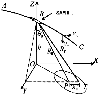
[0036] Such as figure 1 As shown, the flight carrier SAR model is established. The aircraft flies along the arc ABC in the XOZ plane of the earth coordinate system, assuming that point B is located at the azimuth slow time t m equal to zero moment, that is, t m = 0, at this time the flight height of the aircraft is h, the intersection point of the beam center line and the ground plane XOY is P, and this point is taken as the center point of the scene, a conical coordinate system is equivalently established, and the corresponding beam center slant distance is R 0 , the angle between BP and YOZ plane is the oblique angle, denoted as θ. The velocity and acceleration along the X axis are v x , a x ; Velocity and acceleration along the Z axis are vz , a z .

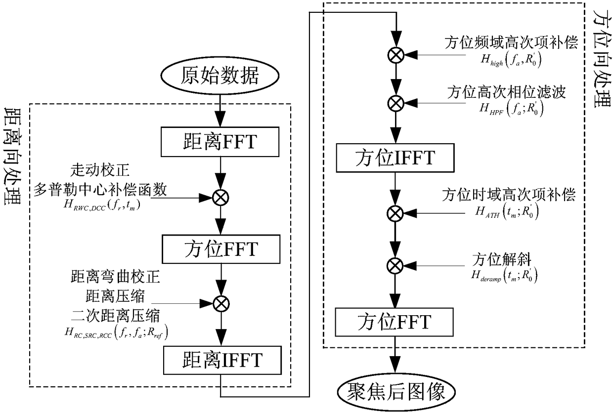
[0037] Specific imaging process such as figure 2 shown in the following steps:

[0038...


PUM


Abstract

The invention proposes an SAR imaging method, and the method comprises the steps: carrying out the collection of SAR data, range direction compensation, azimuth frequency domain high-order term compensation, azimuth frequency domain high-order phase filtering, azimuth time domain high-order term compensation and azimuth inclination correction, and obtaining an image after focusing. The method is used for aperture data processing, gives consideration to the frequency modulation rate space variant caused by the range envelope and azimuth target position at the same time on the basis of the high-order approximate two-dimensional spectrum, employs a frequency domain high-order phase filtering method for solving, effectively improves the imaging speed, and can meet the requirements of real-timeimaging on the basis that the imaging precision is guaranteed.

Description

technical field [0001] The invention relates to a SAR imaging method and belongs to the technical field of precision guidance. Background technique [0002] As a microwave active imaging system, synthetic aperture radar (SAR) has the advantages of all-day, all-weather and high-resolution imaging. Applying SAR imaging technology to the active radar seeker can enhance its precision guidance autonomy and anti-jamming ability in complex battlefield environments. The most common application of the flight platform SAR system in the mid-guidance stage is to correct the trajectory and INS errors through scene matching, which is an effective measure to improve the guidance accuracy and has become the main direction of current SAR imaging applications. [0003] Restricted by the space and load of the platform, the size of the SAR antenna is generally small, so that its full-aperture azimuth resolution is much higher than that of the matching reference image. In practical application...

Claims


Application Information

Patent Timeline
Patent Type & Authority Applications(China)
IPC IPC(8): G01S13/90
CPCG01S13/904G01S13/9047G01S13/9041
Inventor 赵欣王友成杜敦伟李珊钱红庆宋闯
Owner BEIJING RES INST OF MECHANICAL & ELECTRICAL TECH
Why Eureka
Try Eureka