V-shaped flow guiding groove diffuser for draught fan

A technology of diffusers and diversion grooves, which is applied in the direction of machines/engines, mechanical equipment, liquid fuel engines, etc., which can solve the problems of fan surge, large impact loss, separation loss, etc., to reduce friction loss and shorten air flow The effect of distance

Inactive Publication Date: 2018-05-29
NINGBO FEIERGE ELECTROMECHANICAL TECH CO LTD
View PDF0 Cites 0 Cited by
  • Summary
  • Abstract
  • Description
  • Claims
  • Application Information

AI Technical Summary

Problems solved by technology

In addition, under the design conditions, the vane diffuser is 3~5% more efficient than the vaneless diffuser, but the impact loss of the vane diffuser is large due to the existence of the vane, and the separation loss is easy to occur when the attack angle increases, resulting in Fan surge

Method used


Image

  • V-shaped flow guiding groove diffuser for draught fan
  • V-shaped flow guiding groove diffuser for draught fan

Examples


Embodiment Construction

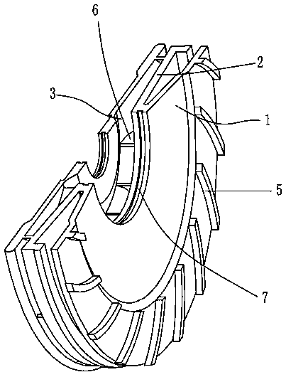
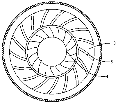
[0010] The present invention will be described in further detail below in conjunction with accompanying drawing and specific embodiment: see Figure 1 to Figure 2 , a fan V-shaped guide groove diffuser, including a first annular plate body 1, a second annular plate body 2, a third annular plate body 3, the middle of the diffuser is used to set the impeller 4, the first annular plate body The outer ring of an annular plate body 1 is provided with a first arc-shaped flow guide strip 5, and the gap between two adjacent first arc-shaped flow guide strips 5 gradually expands from the inside to the outside, and the second annular plate The body 2 and the third annular plate body 3 are connected by a second arc-shaped guide bar 6, and the second arc-shaped guide bar 6 extends outward from the center of the impeller 4, and the impeller 4 is a copper alloy, composed of 70 % copper, 20% manganese, and 10% silicon are mixed and fired, and the gap between the two adjacent second arc-shape...


PUM


Abstract

The invention discloses a V-shaped flow guiding groove diffuser for a draught fan. The V-shaped flow guiding groove diffuser for the draught fan comprises a first annular plate body, a second annularplate body and a third annular plate body; an impeller is arranged in the middle of the diffuser; first arc-shaped flow guiding strips are arranged on the outer circle on the first annular plate body;a gap between every two adjacent first arc-shaped flow guiding strips is gradually enlarged from inside to outside; the second annular plate body and the third annular plate body are connected through second arc-shaped flow guiding strips; the second arc-shaped flow guiding strips extend outwards with the impeller as the center; and a gap between every two adjacent second arc-shaped flow guidingstrips is gradually enlarged from inside to outside. According to the V-shaped flow guiding groove diffuser for the draught fan, air flow flows outwards along gaps between the first arc-shaped flow guiding strips and the second arc-shaped flow guiding strips, the flowing path of the air flow is greatly shortened, the friction loss is reduced, to a certain extent, the diffusion degree is increasedand the radial size of the diffuser is reduced, and a complicated structure of a blade diffuser is avoided. The defect that a bladeless diffuser is low in efficiency is also overcome, and the beneficial effects of the blade diffuser and the bladeless diffuser are combined.

Description

technical field [0001] The invention relates to the technical field of fans, in particular to a V-shaped diffuser for fans, which is used for multi-stage centrifugal blowers to improve efficiency and save energy. Background technique [0002] In the multi-stage centrifugal blower, the main function of the diffuser is to decelerate the airflow with large kinetic energy from the impeller, so that the kinetic energy can be effectively converted into pressure energy. Especially for impellers with high-energy heads, the outlet air velocity can reach more than 500m / s, while the outlet air velocity of general impellers is also 200 ~ 300m / s. For radial straight blade impellers, this part of kinetic energy almost accounts for the impeller consumption. half of the work. About 25-40% of the back-curved or strong back-curved impellers. So it has to be put to good use. Commonly used diffusers include the following two types of vaneless diffusers: the common one is composed of an annul...

Claims


Application Information

Patent Timeline
IPC IPC(8): F04D29/44
CPCF04D29/441
Inventor 赵广静
Owner NINGBO FEIERGE ELECTROMECHANICAL TECH CO LTD
Why Eureka
Try Eureka