Improved new energy charging pile device

A charging pile and new energy technology, applied in charging stations, coupling devices, electric vehicle charging technology, etc., can solve the problems of being easily contacted by metal sheets or metal rods, hidden dangers, single setting mode, etc., to increase charging safety effect

Inactive Publication Date: 2018-06-26
NINGBO CITY DAZHIFENG IND PROD DESIGN CO LTD
View PDF0 Cites 5 Cited by
  • Summary
  • Abstract
  • Description
  • Claims
  • Application Information

AI Technical Summary

Problems solved by technology

Charging piles are supporting facilities for new energy vehicles and are the carrier for charging new energy vehicles. However, the traditional charging piles have a single setting mode, and the charging process only depends on the friction force when the charging terminal and the charging terminal are plugged in to keep the state of motion. , if you accidentally touch the charging terminal or be affected by the pulling of the charging cable, it may cause the charging terminal to fall off, resulting in charging interruption. In addition, traditionally, the conductive sheet inside the charging terminal is generally set relatively outside , this kind of conductive sheet is easily contacted by metal sheets or metal rods. Therefore, when people who lack safety awareness insert metal sheets or metal rods into the charging terminal, electric shock accidents are likely to occur, which is likely to cause casualties. There is a big security risk

Method used


Image

  • Improved new energy charging pile device
  • Improved new energy charging pile device
  • Improved new energy charging pile device

Examples


Embodiment Construction

[0022] All features disclosed in this specification, or steps in all methods or processes disclosed, may be combined in any manner, except for mutually exclusive features and / or steps.

[0023] Any feature disclosed in this specification (including any appended claims, abstract and drawings), unless expressly stated otherwise, may be replaced by alternative features which are equivalent or serve a similar purpose. That is, unless expressly stated otherwise, each feature is one example only of a series of equivalent or similar features.

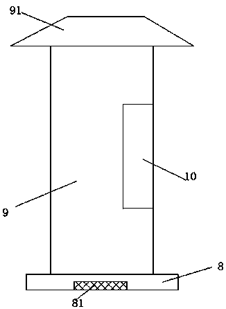
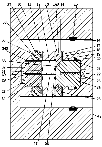
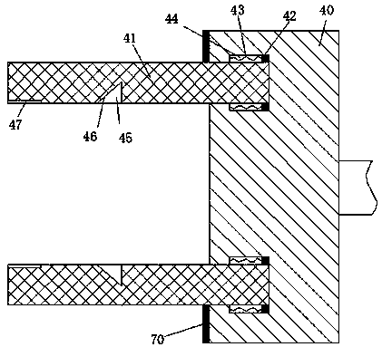
[0024] like Figure 1 to Figure 5As shown, an improved new energy charging pile device of the device of the present invention includes a charging pile body 9, a charging terminal 10 disposed in the right end surface of the charging pile body 9, and a charging terminal connected to a new energy vehicle 40, the bottom of the charging pile body 9 is fixed with a base 8, and the inner bottom of the base 8 is provided with a counterweight 81, and ...


PUM


Abstract

The invention discloses an improved new energy charging pile device. The improved new energy charging pile device comprises a charging pile body, a charging end portion disposed in the end surface ofthe right side of the charging pile body and a charging end socket connected with a new energy vehicle. The bottom of the charging pile body is fixedly provided with a base, the inner bottom of the base is provided with a counterweight block, and the top of the charging pile body is fixedly provided with a rainproof shed. Inserting holes of which through openings face right are formed in the charging end portion in an up-down corresponding mode, and a sliding cavity extending left and right is formed between the two inserting holes in the charging end portion. A left sliding block and a rightsliding block which can smoothly slide left and right are installed in the sliding cavity, the right end surface of the left sliding block is up-down correspondingly provided with power transmission heads connected with mains supply, and the left end surface of the right sliding block is provided with electric connection heads matched with the power transmission heads in an up-down corresponding mode.

Description

technical field [0001] The invention relates to the technical field of new energy vehicles, in particular to an improved new energy charging pile device. Background technique [0002] New energy vehicles are gradually replacing traditional vehicles with many advantages such as energy saving, environmental protection and pollution-free, and are widely used. The charging pile is a supporting facility for new energy vehicles, and it is the carrier for charging new energy vehicles. However, the traditional charging pile setting mode is single, and the charging process only relies on the friction force when the charging terminal and the charging terminal are plugged in to keep the state. , if you accidentally touch the charging terminal or be affected by the pulling of the charging cable, it may cause the charging terminal to fall off, resulting in charging interruption. In addition, traditionally, the conductive sheet inside the charging terminal is generally set relatively outs...

Claims


Application Information

Patent Timeline
Patent Type & Authority Applications(China)
IPC IPC(8): B60L11/18H01R13/639
CPCB60L53/31H01R13/639Y02T10/70Y02T10/7072Y02T90/12
Inventor 邵林肖
Owner NINGBO CITY DAZHIFENG IND PROD DESIGN CO LTD
Why Eureka
Try Eureka