Bearing lubricating device

A bearing lubrication and sliding hole technology, which is applied to bearing elements, shafts and bearings, and devices that apply liquid to surfaces, etc., can solve problems such as uneven lubrication and improve the effect of oiling.

Inactive Publication Date: 2018-07-06
重庆婉婷科技发展有限公司
View PDF13 Cites 5 Cited by
  • Summary
  • Abstract
  • Description
  • Claims
  • Application Information

AI Technical Summary

Problems solved by technology

[0003] The purpose of the present invention is to provide a bearing lubri

Method used


Image

  • Bearing lubricating device
  • Bearing lubricating device
  • Bearing lubricating device

Examples


Embodiment Construction

[0016] The following is further described in detail through specific implementation methods:

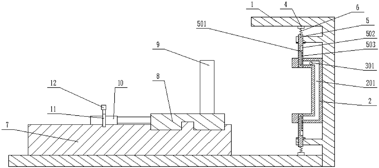
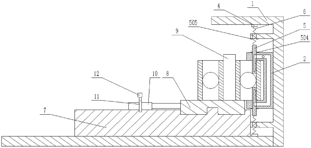
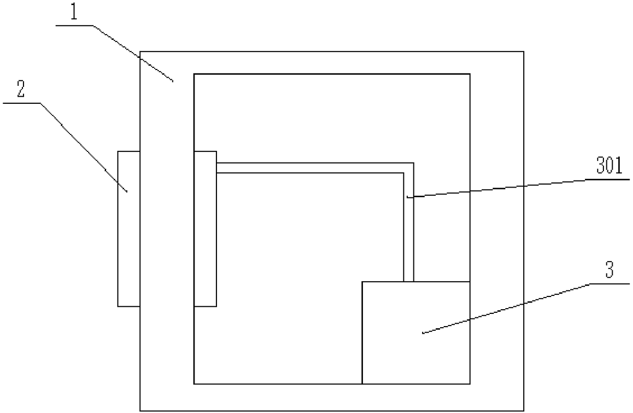
[0017] The reference signs in the drawings of the description include: frame 1, support base 2, first diversion hole 201, fuel tank 3, oil inlet pipe 301, electromagnet 4, oiling rod 5, second diversion hole 501, communication hole 502, oil outlet hole 503, block 504, magnet 505, extension spring 6, mobile platform 7, rotary platform 8, positioning shaft 9, runner 10, rotating shaft 11, motor 12.

[0018] The embodiment is basically as attached figure 1 , attached figure 2 And attached image 3 Shown:

[0019] The bearing lubricating device includes a frame 1, a lubricating part and a rotating part. A slide rail is horizontally arranged on the frame 1. The lubricating part includes an oil tank 3, a support seat 2 and two oiling units symmetrically arranged up and down on the horizontal axis of the support seat 2. , the support seat 2 is in the shape of "匚", the support seat 2 is...


PUM


Abstract

The invention belongs to the field of machine repair, and particularly relates to a bearing lubricating device. The bearing lubricating device comprises a machine frame, a lubricating portion and a rotary portion. A sliding rail is arranged on the machine frame. The lubricating portion comprises a supporting seat, an oil tank and two or more oiling units symmetrically arranged relative to the axisof the supporting seat, a first flow guide hole is formed in the supporting seat, and the oil tank is provided with an oil inlet pipe communicating with the first flow guide hole. Each oiling unit comprises an electromagnet fixed to the machine frame, an oiling bar connected with the machine frame in a sliding mode and a sliding hole formed in the supporting seat, wherein a tension spring is fixed between one end of the oiling bar and the electromagnet, the other end of the oiling bar extends into the sliding hole, an oil outlet and a second flow guide hole capable of communicating with the first flow guide hole are formed in the oiling bar, and the oil outlet communicates with the second flow guide hole. The rotary portion comprises a moving table, a rotary table and a rotary wheel, themoving table can slide on the sliding rail, the rotary table is rotationally connected with the moving table, a positioning shaft is arranged on the rotary table, and the rotary wheel and the rotary table are in belt transmission. By means of the scheme, the problem of non-uniform lubrication in the prior art is solved.

Description

technical field [0001] The invention belongs to the field of mechanical maintenance, in particular to a bearing lubricating device. Background technique [0002] When the bearing on the gearbox of construction machinery is working, there is a high relative motion speed between the inner and outer rings of the bearing, which needs to be lubricated. The bearing lubrication on the gearbox usually adopts oil-through lubrication, that is, the lubricating oil passes through the bearing along the inner and outer rings of the bearing. The amount of lubricating oil passed determines the quality of the lubricating effect. Only a small part of the lubricating oil that the mechanism flows out from the oil hole passes between the inner and outer rings of the bearing to effectively lubricate the bearing, the lubricating effect is poor, and a large amount of lubricating oil is wasted. Contents of the invention [0003] The object of the present invention is to provide a bearing lubricat...

Claims


Application Information

Patent Timeline
IPC IPC(8): B05C1/06B05C7/06B05C11/10F16C33/66
CPCF16C33/6637B05C1/06B05C7/06B05C11/1039
Inventor 姚雪儒欧阳婧芸何婉亭何明黄月朋宇
Owner 重庆婉婷科技发展有限公司
Why Eureka
Try Eureka