Part cooling device

A technology for cooling devices and parts, applied in the field of parts cooling devices, can solve the problems of partial cooling where parts cannot be in contact with the conveyor belt, less air flow in the cooling chamber, and poor cooling effect, etc., and achieve simple structure and faster speed. The effect of air flow and low manufacturing cost

Inactive Publication Date: 2018-08-17
宁波鑫神泽汽车零部件有限公司
View PDF3 Cites 0 Cited by
  • Summary
  • Abstract
  • Description
  • Claims
  • Application Information

AI Technical Summary

Problems solved by technology

[0004] The above scheme achieves rapid cooling of injection molded parts through the setting of the cooling chamber, but this device still has the following problems: During the cooling process, since the bottom of the parts is always in contact with the con...

Method used


Image

  • Part cooling device
  • Part cooling device

Examples


Embodiment Construction

[0020] The present invention will be described in further detail below by means of specific embodiments:

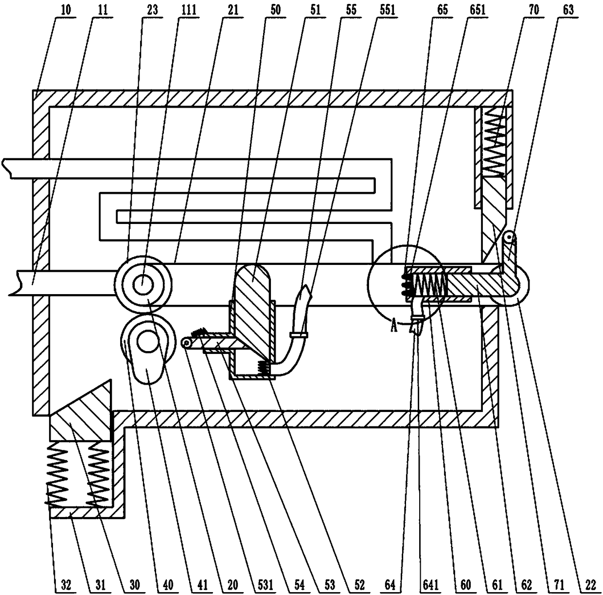
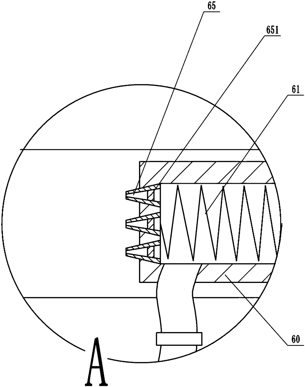
[0021] Instructions attached Figures 1 to 2 The reference signs in include: cooling chamber 10, cooling water pipe 11, transmission shaft 111, driving wheel 20, conveyor belt 21, driven wheel 22, first gear 23, wedge 30, support plate 31, fourth spring 32, the first Two gears 40, cam 41, piston barrel 50, plunger 51, first spring 52, push rod 53, roller 531, extension spring 54, exhaust pipe 55, one-way exhaust valve 551, spray tube 60, second spring 61, pressure post 62, push post 63, water inlet pipe 64, one-way water inlet valve 641, conical spray pipe 65, one-way drain valve 651, third spring 70, gate 71.

[0022] like figure 1As shown, the component cooling device includes a cooling chamber 10 , a conveying unit, a discharge unit, and a tightening unit and a spraying unit both located in the cooling chamber 10 . The transmission unit includes a driving wheel 20, ...


PUM


Abstract

The invention belongs to the technical field of part production equipment, and particularly discloses a part cooling device. The device comprises a cooling chamber, a cooling water pipe is fixed in the cooling chamber, and a mist spraying unit, an ejecting unit and a conveying unit are further included, the conveying unit comprises a driving wheel, a driven wheel, a driven shaft and a conveying belt, a turbine is rotatably connected in the cooling water pipe, and is coaxially connected with a transmission shaft, the transmission shaft is fixed to the driving wheel, the driving wheel is coaxially connected with a first gear, the ejecting unit comprises a piston cylinder and a second gear, a plunger is in sliding connection into the piston cylinder, a first spring is connected between the plunger and the piston cylinder, an inclined face is arranged on the lower surface of the plunger, a push rod is in sliding connection to the side wall of the piston cylinder, an exhaust pipe is connected with the lower portion of the piston cylinder, the mist spraying unit comprises a mist spraying cylinder, a pressure column is in sliding connection into the mist spraying cylinder, and a conical mist spraying pipe is connected to the mist spraying cylinder. Through the cooling device, the bottoms of parts can be effectively cooled, and the cooling effect is improved.

Description

technical field [0001] The invention belongs to the technical field of component production equipment, and in particular relates to a component cooling device. Background technique [0002] Many existing auto parts are formed by injection molding. The injection molding parts are formed by the injection molding machine and then taken out of the mold. After demoulding, the temperature is relatively high, generally around 60°C, and it needs to be cooled before it can be processed. A production process, and if it is placed in the air to cool naturally, but natural cooling takes a lot of time and affects production efficiency. [0003] In order to solve the above problems, the invention patent with the Chinese patent application number 201510347907.X discloses a cooling device for automotive injection molding parts, which includes a box-like structure composed of two vertical plates on the left and right and two horizontal plates on the upper and lower sides. The horizontal plat...

Claims


Application Information

Patent Timeline
IPC IPC(8): B29C45/72
Inventor 王健
Owner 宁波鑫神泽汽车零部件有限公司
Why Eureka
Try Eureka