Wind-induced internal pressure testing method oriented to punched flexible building

A test method and internal pressure technology, applied in special data processing applications, instruments, electrical digital data processing, etc., can solve problems such as deviation from single resonance response, double peak resonance of internal pressure response, deviation of wind pressure test results, etc.

Active Publication Date: 2018-08-21
ZHEJIANG UNIV
View PDF5 Cites 6 Cited by
  • Summary
  • Abstract
  • Description
  • Claims
  • Application Information

AI Technical Summary

Problems solved by technology

Because for flexible open buildings (such as membrane structure buildings, industrial plants, etc.), under the joint action of internal and external wind pressure, the structural deformation will cause corresponding changes in its internal volume, and the classic volume adjustment method cannot consider The impact of this change, therefore, cannot be applied to the internal pressure test of this type of structure
[0004] In the past, the classic scale effect correction theory simply gave the conclusion that the model needs to be adjusted according to the square of the wind speed ratio during the internal pressure test, but there are still many problems in the actual test operation process, which often leads to unexpected test results
For example, regarding the connection between the regulating device and the test model, when a small connection hole is used between the two, the measured internal pressure will have the characteristics of double-peak resonance, which deviates from the characteristics of the single resonance response of the original building internal pressure
In addition, the shape of the regulating device, such as the height, also has a significant impact on the test results of the internal pressure. When an excessively high regulating container is used, the phenomenon of double-peak resonance in the internal pressure response will also occur, resulting in deviations in the test results of the wind pressure in the building.

Method used


Image

  • Wind-induced internal pressure testing method oriented to punched flexible building
  • Wind-induced internal pressure testing method oriented to punched flexible building
  • Wind-induced internal pressure testing method oriented to punched flexible building

Examples


Embodiment Construction

[0059] Embodiments of the present invention will be described in detail below in conjunction with the accompanying drawings. This embodiment is developed on the basis of the technical solution of the present invention, but the protection scope of the present invention is not limited to the following embodiments.

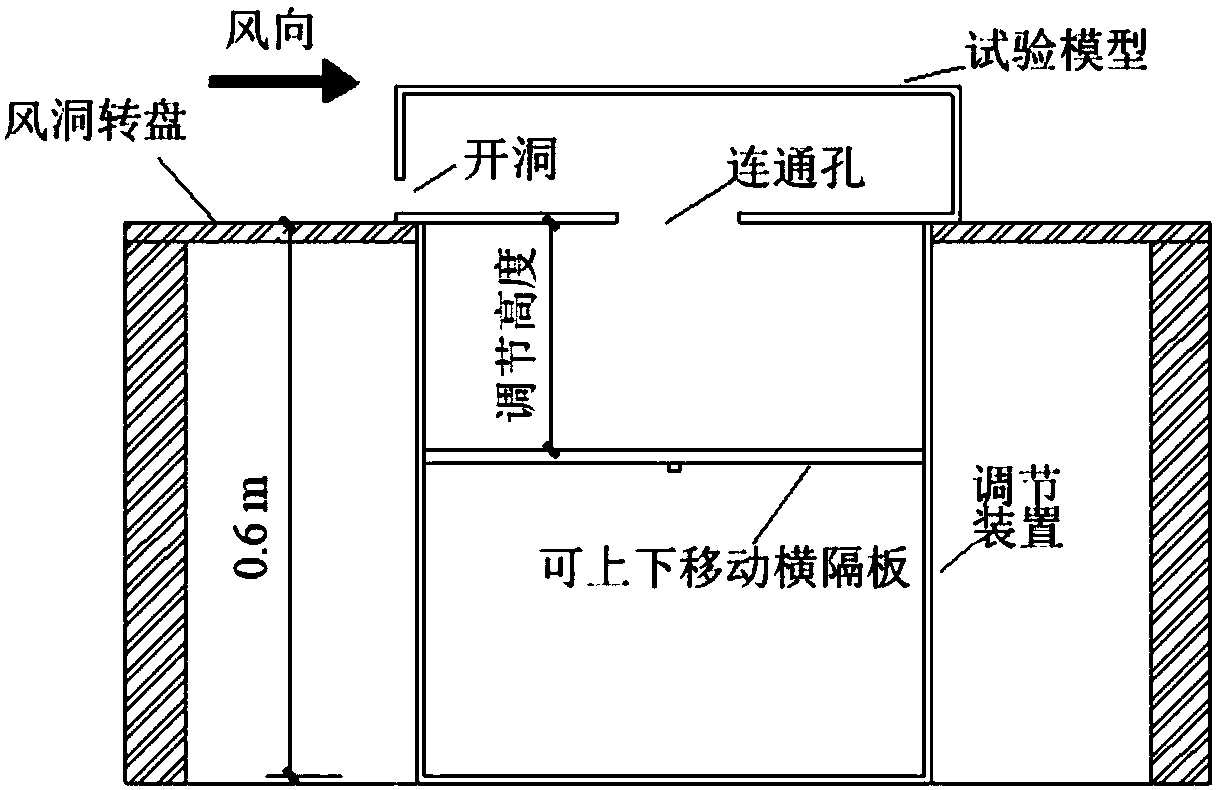
[0060] The building in this embodiment is a single-story factory building located in the coastal area. There is a leading opening of 25m×50m on one side wall of the factory building. The length, width and height of the factory building are respectively: 137m×91m×40m. The landform is Class B landform in the load specification (GB50009-2012). In the wind tunnel test, the geometric scale ratio of the model to the prototype λ l =1:250, the wind speed ratio is λ l =1:2.

[0061] According to the inventive method, the concrete test method of the internal pressure of this building is as follows:

[0062] Step 1): First, according to the building structure information, u...


PUM


Abstract

The invention belongs to the field of the wind resistance of an engineering structure, and particularly relates to a wind-induced internal pressure testing method oriented to a punched flexible building. The invention provides the wind-induced internal pressure testing method oriented to the punched flexible building. A building model is subjected to internal volume correction, a regulation deviceis reasonably selected, so that the problem of experiment test errors brought by the reduced scale effect of the punched flexible building model is solved, an internal pressure resonance frequency test deviation caused by model reduced scale is reduced, the test distortion of internal pressure response is lowered, the reliability of a model experiment result is improved, the pulse response of aninternal wind load after the flexible building is punched can be accurately measured, and a dereferencing basis is provided for engineering wind-resistant design.

Description

technical field [0001] The invention belongs to the field of wind resistance of engineering structures, and in particular relates to a wind-induced internal pressure test method for flexible buildings with openings. Background technique [0002] When a building has local openings due to functional requirements or wind-induced damage, significant internal pressure fluctuations will occur inside the building, which may even exceed the corresponding external pressure value. When it is superimposed with the wind load acting on the outside of the building, it may greatly increase the total net wind load of the building structure, thereby increasing the risk of structural damage. A large number of wind disaster surveys have shown that the synergy of internal and external pressure is one of the main reasons for building damage under strong winds. Therefore, for buildings with openings, it is of great engineering significance to accurately evaluate the wind-induced internal pressur...

Claims


Application Information

Patent Timeline
Patent Type & Authority Applications(China)
IPC IPC(8): G06F17/50
CPCG06F30/13G06F30/23G06F2119/06
Inventor 徐海巍楼文娟
Owner ZHEJIANG UNIV
Why Eureka
Try Eureka