Garbage waste gas deodorization device

A technology for waste gas and waste, applied in the field of waste gas deodorization devices, can solve problems such as waste gas treatment, and achieve the effect of high surface energy

Pending Publication Date: 2018-09-25
SI CHUAN RUI YUAN ENERGY & ENVIRONMENT TECH
View PDF6 Cites 1 Cited by
  • Summary
  • Abstract
  • Description
  • Claims
  • Application Information

AI Technical Summary

Problems solved by technology

However, most of the existing garbage transfer stations have not treated the waste gas generated by the garbage due to site constraints.

Method used


Image

  • Garbage waste gas deodorization device

Examples


Embodiment

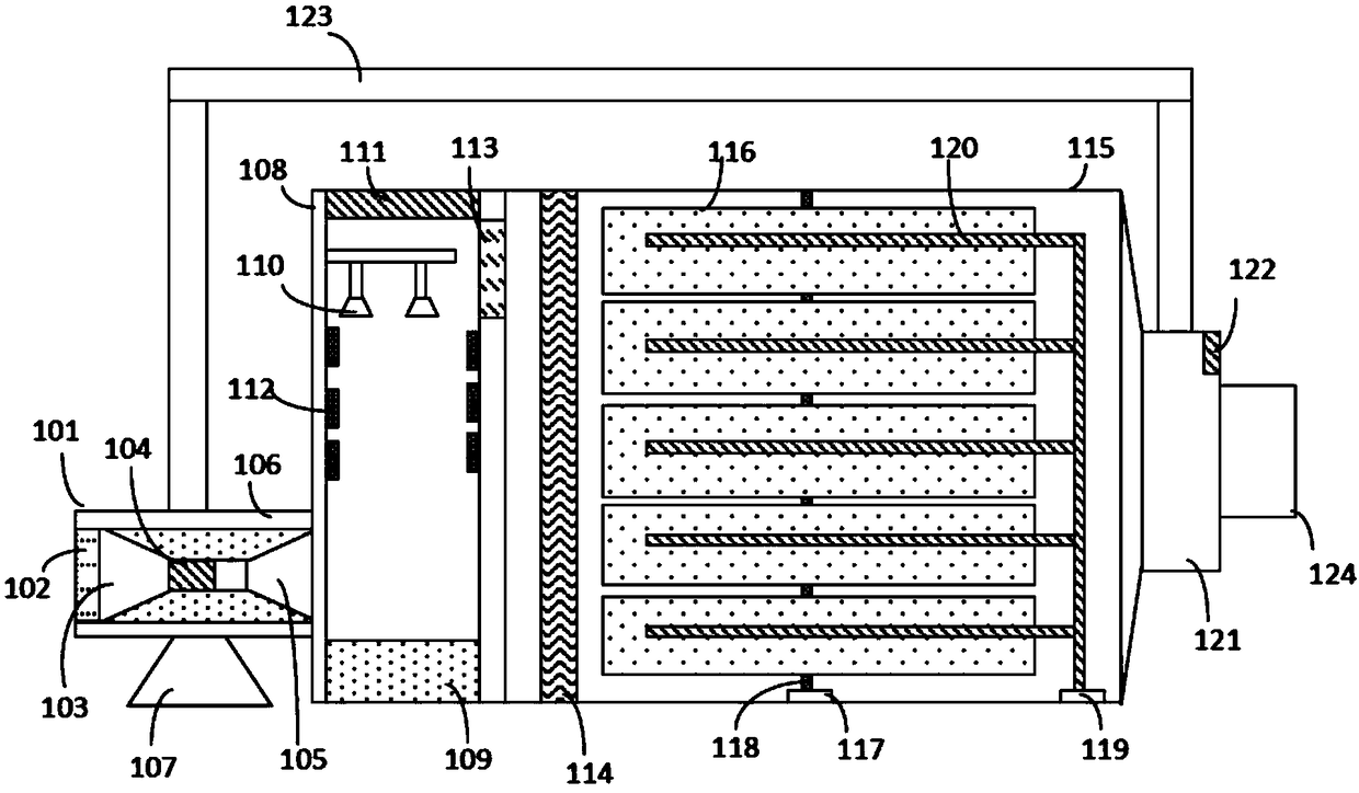
[0021] A waste gas deodorization device, such as figure 1 shown. The deodorizing device includes a waste gas collection part 101 , a primary treatment chamber 108 , an equalizer 114 , a photoelectric catalytic chamber 115 and an exhaust part 121 . The waste gas collecting part 101 is connected with the primary processing chamber 108 , and the primary processing chamber 108 is connected with the photoelectric catalytic chamber 115 through the equalizer plate 114 . The photoelectric catalytic chamber 115 is also connected with an exhaust part 121 . The waste gas collecting part 101 is used to realize the bad smell in the garbage storage box. The primary treatment chamber 108 is used to complete the primary impurity removal treatment for the odor. The equalizer plate 114 is used to package the gas to be treated and flow into the photoelectric catalytic chamber 115 uniformly. The exhaust part 121 is used to discharge the processed gas.

[0022] Preferably, the waste gas colle...


PUM


Abstract

The invention discloses a garbage waste gas deodorization device. The deodorization device at least comprises a photoelectrocatalytic chamber, wherein the photoelectrocatalytic chamber at least comprises an anode terminal, a cathode terminal, a cathode needle and an anode barrel which is arranged in parallel; the surface of the anode barrel is covered with a TiO2 nano layer and is connected with the anode terminal through a connection part; the cathode needle is located at the axis position of the anode barrel and is connected with the cathode terminal through a conductor; a strip-shaped lightsource is spirally arranged on the surface layer of the cathode needle. By adopting the device disclosed by the invention, an efficient waste gas treatment process is finished through miniaturized equipment.

Description

technical field [0001] The invention relates to the field of gas deodorization, in particular to a garbage waste gas deodorization device. Background technique [0002] The environmental pollution caused by the discharge of municipal solid waste and its proper management are one of the urgent problems to be solved in our country. With the development of society and production, more and more garbage will be generated. Taking Chengdu as an example, in 2005, about 2,000 tons of household garbage were generated every day. By 2014, the daily household garbage generated was about 3,950 tons. . With the increase of Yantai's urban population, the continuous improvement of citizens' living standards and the integration of urban and rural areas, the domestic waste in Chengdu has almost doubled in the past ten years. [0003] With the continuous strengthening of people's awareness of environmental protection, people are required to process and dispose of garbage more scientifically. ...

Claims


Application Information

Patent Timeline
Patent Type & Authority Applications(China)
IPC IPC(8): B01D53/86B01D53/78B01D47/06
CPCB01D47/06B01D53/007B01D53/32B01D53/78B01D53/86B01D2251/10B01D2255/802B01D2259/804B01D2257/406B01D2257/93B01D2257/91B01D2257/7027B01D2257/708B01D2257/90B01D2258/0291
Inventor 覃勋蒋东芮
Owner SI CHUAN RUI YUAN ENERGY & ENVIRONMENT TECH
Why Eureka
Try Eureka