Manufacturing method of aerial fog generation device

A production method and aerosol generation technology, which are applied in the fields of application, tobacco, and smoker’s products, can solve the problems of practical operation difficulties, inconsistent products, and high labor costs, and achieve long service life, large contact area, and cost savings. Effect

Active Publication Date: 2018-11-06
深圳市颢帆科技有限公司
View PDF6 Cites 3 Cited by
  • Summary
  • Abstract
  • Description
  • Claims
  • Application Information

AI Technical Summary

Problems solved by technology

[0002] A currently used electronic cigarette atomizer includes a housing, an atomizer, an oil storage bin, a battery assembly, and a control assembly. The atomizer includes a sheet-shaped heating wire and oil-conducting cotton. The atomizer There are air inlet holes and oil inlet holes in the middle, the oil inlet holes are connected to the oil storage tank, and the air inlet holes are connected to the outside world. The oil guide cotton absorbs the smoke oil to the heating wire through the oil inlet holes for atomization of the heating wire, and the battery The component is connected to the control

Method used


Image

  • Manufacturing method of aerial fog generation device
  • Manufacturing method of aerial fog generation device
  • Manufacturing method of aerial fog generation device

Examples


Embodiment Construction

[0030] The following will clearly and completely describe the technical solutions in the embodiments of the present invention with reference to the accompanying drawings in the embodiments of the present invention. Obviously, the described embodiments are only some, not all, embodiments of the present invention. Based on the embodiments of the present invention, all other embodiments obtained by persons of ordinary skill in the art without making creative efforts belong to the protection scope of the present invention.

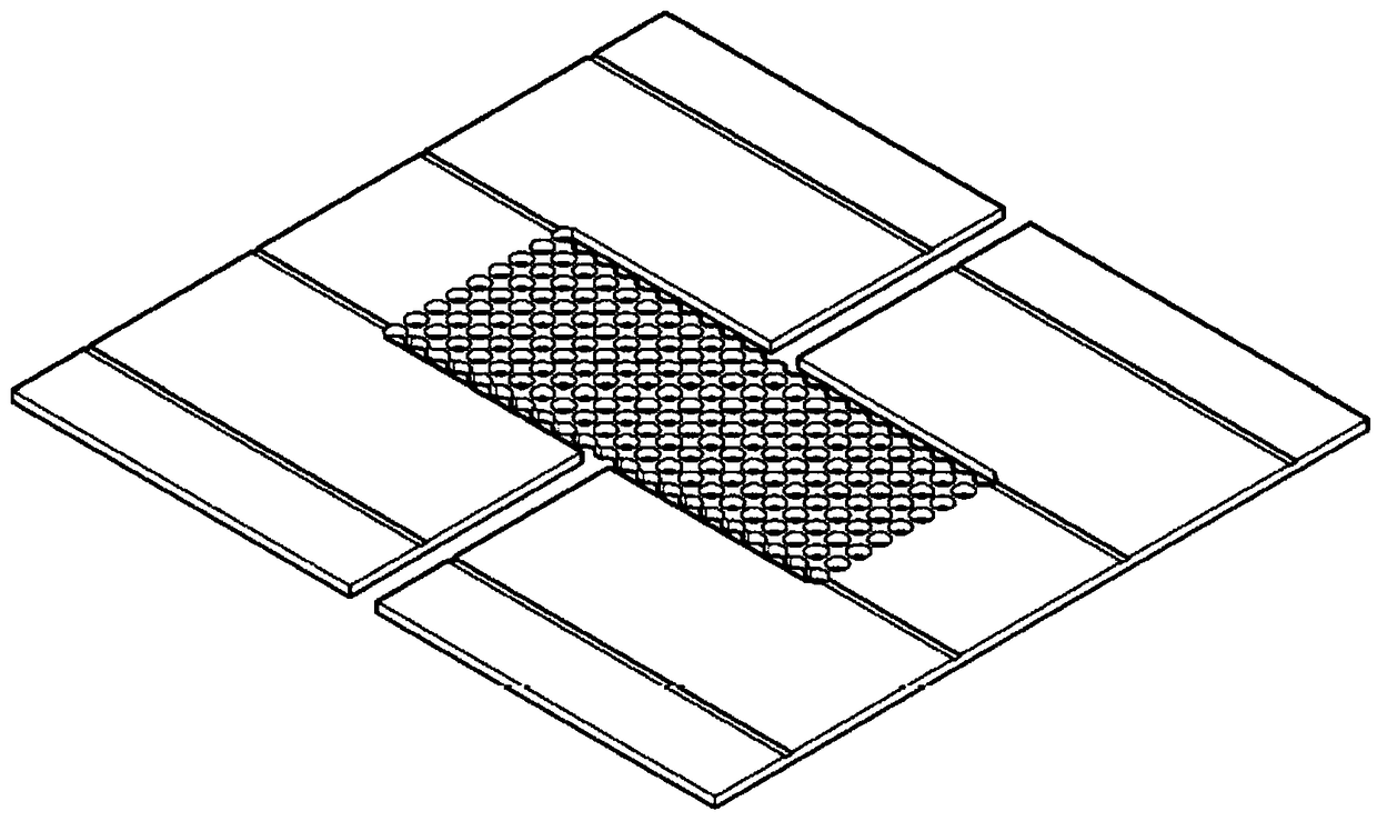
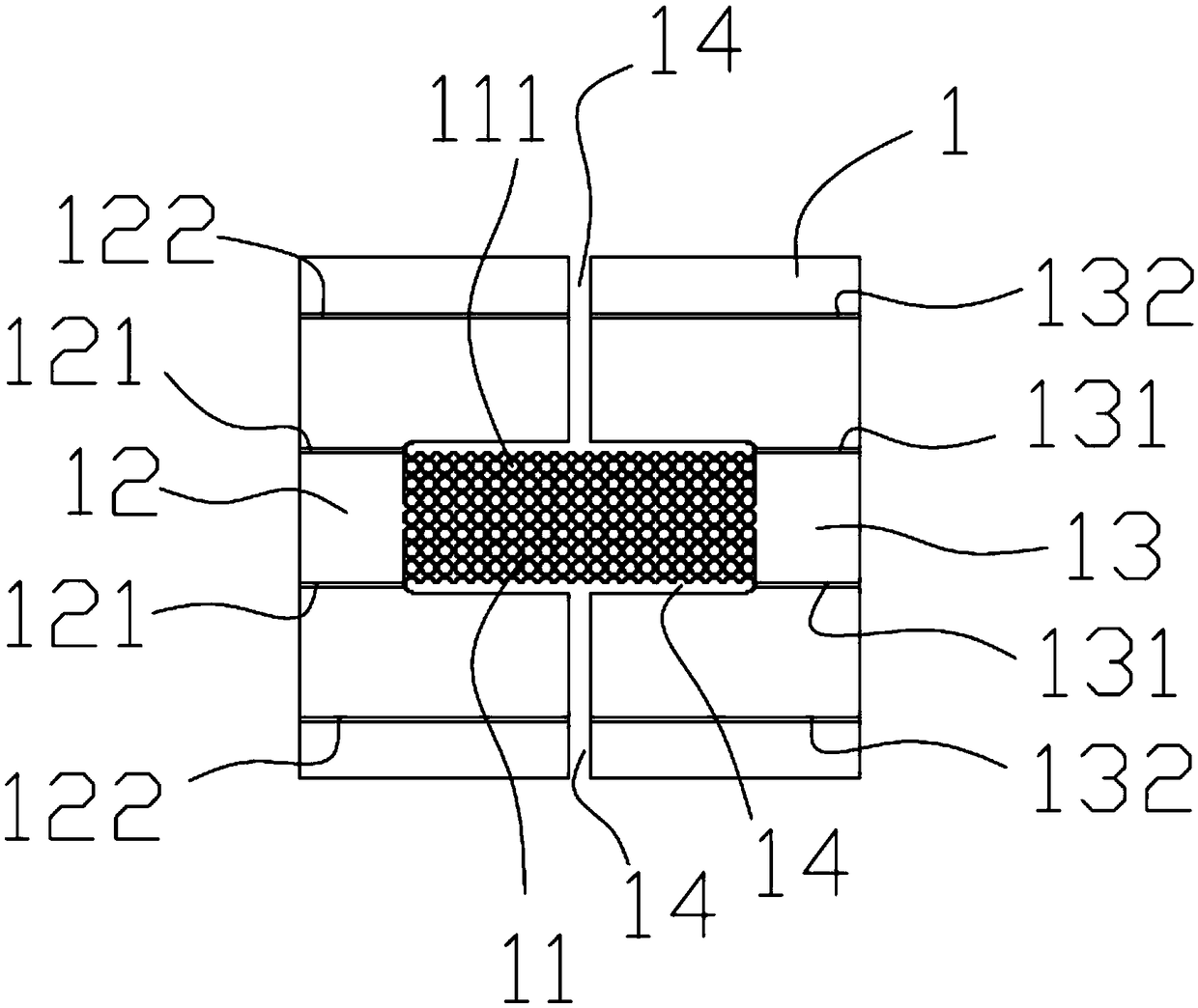
[0031] Such as Figure 1-Figure 9 , the embodiment of the present invention provides a method for manufacturing an aerosol generating device, which includes the following steps:

[0032] a. Provide a plate body 4 (also known as a metal substrate), and carry out surface treatment on the plate body 4. The surface treatment includes removing the oxide film on the surface of the plate body 4, cleaning, drying, and coating on the upper and lower sides of the plate ...


PUM


Abstract

The invention provides a manufacturing method of an aerial fog generation device. The method includes the steps that a plate body is provided and subjected to surface treatment, wherein surface treatment includes removal of oxide films on the surface of the plate body, cleaning, drying and coating of protective films on the upper and lower sides of the plate body; a plate is manufactured; the surface of the plate body is coated with the obtained plate; exposure, baking and etching are carried out; cleaning and demolding are carried out to obtain a primary base plate, wherein the primary base plate comprises a heating area, a first electrode area and a second electrode area, a plurality of mesh holes are formed in the heating area, and the first electrode area and the second electrode areaare isolated from each other and electrically independent; an oil guide element is provided, the heating area is attached to the surface of the oil guide element, so that the bent first electrode areawraps one side of the oil guide element, and the bent second electrode area wraps the other side of the oil guide element. Mechanical work of heating pieces is achieved, large-scale production is achieved, the cost is low, and compared with a manual operation mode, the cost is greatly reduced.

Description

technical field [0001] The invention relates to a manufacturing method of an aerosol generating device. Background technique [0002] A currently used electronic cigarette atomizer includes a housing, an atomizer, an oil storage bin, a battery assembly, and a control assembly. The atomizer includes a sheet-shaped heating wire and oil-conducting cotton. The atomizer There are air inlet holes and oil inlet holes in the middle, the oil inlet holes are connected to the oil storage tank, and the air inlet holes are connected to the outside world. The oil guide cotton absorbs the smoke oil to the heating wire through the oil inlet holes for atomization of the heating wire, and the battery The component is connected to the control component, and the control component is connected to the heating wire. The heating wire is bent into a spiral shape, and the oil-conducting cotton penetrates into the spiral-shaped heating wire. Insert into the spiral heating wire, because the oil-conduc...

Claims


Application Information

Patent Timeline
IPC IPC(8): A24F47/00
CPCA24F47/008
Inventor 胡廷东谭会民
Owner 深圳市颢帆科技有限公司
Why Eureka
Try Eureka