Power supply equipment and power factor correction circuit thereof

A power factor correction and circuit technology, which is applied in the direction of high-efficiency power electronic conversion, output power conversion devices, electrical components, etc., can solve the problem that the input current of the rectifier bridge cannot follow the change of the input voltage, the power factor of the switching power supply and the total amount of harmonics Unable to meet the requirements, etc.

Pending Publication Date: 2018-11-06
INVENTRONICS HANGZHOU
View PDF9 Cites 8 Cited by
  • Summary
  • Abstract
  • Description
  • Claims
  • Application Information

AI Technical Summary

Problems solved by technology

However, in the switching power supply, there is also a filter capacitor in the front stage of the PFC circuit. When the AC voltage input by the grid is in the zero-crossing time period, the existence of the filter capacitor will make the voltage of the rectifier bridge higher than that of the rectifier bridge. The i

Method used


Image

  • Power supply equipment and power factor correction circuit thereof
  • Power supply equipment and power factor correction circuit thereof
  • Power supply equipment and power factor correction circuit thereof

Examples


Embodiment Construction

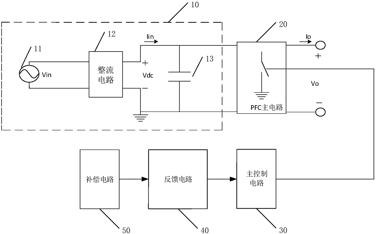
[0057] The core of the present invention is to provide a power factor correction circuit, which avoids the current abnormality caused by the filter capacitor near the zero crossing of the input AC voltage, and then makes the power factor and total harmonics of the switching power supply meet the requirements.

[0058] In order to enable those skilled in the art to better understand the solution of the present invention, the present invention will be further described in detail below in conjunction with the accompanying drawings and specific embodiments. Apparently, the described embodiments are only some of the embodiments of the present invention, but not all of them. Based on the embodiments of the present invention, all other embodiments obtained by persons of ordinary skill in the art without making creative efforts belong to the protection scope of the present invention.

[0059] Please refer to figure 1 , figure 1 It is a structural schematic diagram of a power factor ...


PUM


Abstract

The invention discloses a power factor correction circuit. The circuit comprises a PFC pre-circuit including the AC input, a rectifier circuit and a filter capacitor; a PFC master circuit connected with the PFC pre-circuit; a master control circuit with an output end connected with the PFC master circuit; a feedback circuit with the output end connected with the input end of the master control circuit; and a compensation circuit with the output end connected with the feedback circuit and used for outputting a compensation signal in each preset interval so as to improve the input current of thePFC master circuit through the feedback circuit, wherein each preset interval is the input voltage zero-cross time quantum of the AC input, each preset interval is in periodical change, and the period is same as the period of the input voltage. By applying the scheme disclosed by the invention, the current abnormity caused by the filter capacitor is avoided when the input AC voltage is near the zero-cross, and the power factor and the total harmonic content of the switch power supply satisfy the requirement. The invention further provides power supply equipment with the corresponding effect.

Description

technical field [0001] The invention relates to the technical field of electronic circuit control, in particular to a power supply device and a power factor correction circuit thereof. Background technique [0002] In the power supply system, power factor and total harmonics are important factors to be considered. High power factor and low total harmonics suppress the damage to the system itself and the surrounding environment due to current waveform distortion, which greatly guarantees The use environment of power supply equipment and electrical equipment, the power factor and the total amount of harmonics of various electrical equipment are also increasingly required by national grids. [0003] Existing switching power supplies usually include a PFC (Power Factor Correction, power factor correction) circuit. The commonly used active PFC circuit usually includes a PFC main circuit and related control circuits, which can make its own input current effectively follow the chan...

Claims


Application Information

Patent Timeline
IPC IPC(8): H02M1/42
CPCH02M1/4208Y02B70/10
Inventor 梅进光周可超徐德飞姜德来
Owner INVENTRONICS HANGZHOU
Why Eureka
Try Eureka