

Power triggering circuit
A technology for triggering circuits and power supply circuits, applied in circuits, battery circuit devices, circuit devices, etc., can solve problems such as shortening battery usage time, affecting product experience, and battery power consumption.
Pending Publication Date: 2018-12-11
GREE ELECTRIC APPLIANCES INC
View PDF2 Cites 0 Cited by
- Summary
- Abstract
- Description
- Claims
- Application Information
AI Technical Summary
Problems solved by technology
[0002] At present, the batteries of many products on the market have been installed before leaving the factory. However, some products have loads such as time display that require uninterrupted power supply from the battery. During the period of sale to the user, the power of the battery is consumed, which eventually leads to the shortening of the actual use time of the battery by the user, which affects the product experience
Method used
View moreImage
Smart ImageViewing Examples

Examples
Embodiment 12
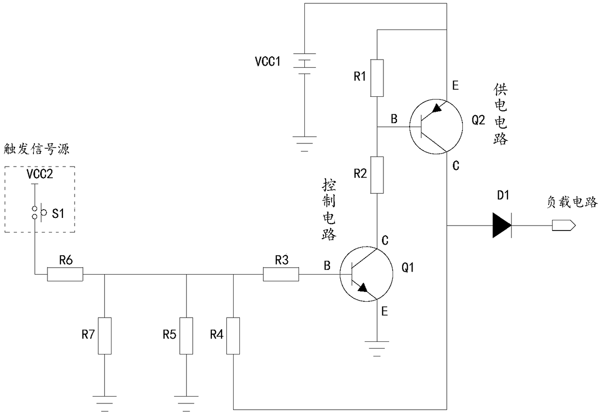
[0050] Embodiment 12 of the present invention is a power trigger circuit. On the basis of Embodiment 10, the button S1 is connected in series with a seventh resistor R7 and grounded, and the seventh resistor R7 can be omitted.
Login to View More PUM
 Abstract
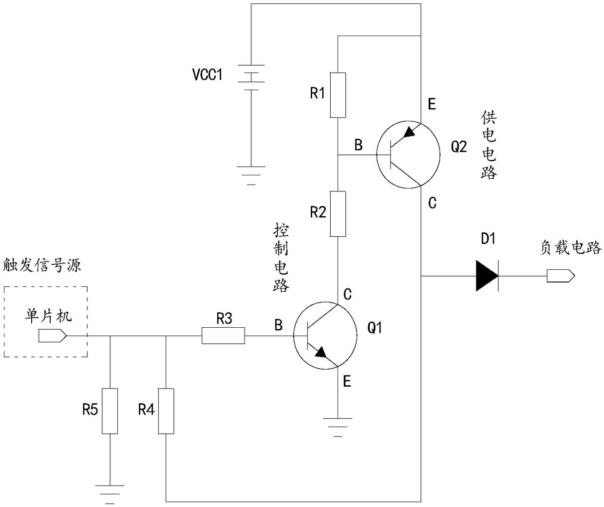
The invention discloses a power triggering circuit, comprising a first power supply, a control circuit and a power supply circuit. The input end of the power supply circuit is connected with the firstpower supply, and the output end of the power supply circuit is connected with the power supply end of the load circuit. The input end of the control circuit is connected with the output end of the trigger signal source, and the output end of the control circuit is connected with the power supply circuit. An output terminal of the power supply circuit is also connected to an input terminal of thecontrol circuit to maintain a high level signal at the input terminal of the control circuit after the power supply circuit is turned on. When the trigger signal source does not give a high-level signal, the first power supply does not supply power to the load circuit and does not consume power. After the trigger signal source gives a high-level signal, the first power supply is supplied to the load circuit for use, and the high-level of the input of the control circuit can be maintained, so that the product can be continuously operated after power-off.
Description
technical field [0001] The invention relates to the technical field of electronic circuits, in particular to a power trigger circuit. Background technique [0002] At present, the batteries of many products on the market have been installed before leaving the factory. However, some products have loads such as time display that require uninterrupted power supply from the battery. During the period of sale to the user, the power of the battery is consumed, which eventually leads to the shortening of the actual use time of the battery by the user and affects the product experience. Contents of the invention [0003] In view of this, one of the objects of the present invention is to provide a power trigger circuit, so as to avoid the consumption of the battery by the product during the period from the factory to the sale to the user. [0004] To achieve the above object, the present invention adopts the following technical solutions: [0005] A power trigger circuit, includi...
Claims
Login to View More Application Information
Patent Timeline
 Patent Type & AuthorityApplications(China)
IPC IPC(8): H02J7/00H03K17/60
CPCH02J7/0063H03K17/60H02J2207/10
Inventor朱永哲贺凯陈定武张博超严朝磊雷志皓
OwnerGREE ELECTRIC APPLIANCES INC