A switch cabinet drawer push-pull structure

A kind of technology of switch cabinet and drawer

Active Publication Date: 2019-01-08
广东求精电气有限公司
View PDF16 Cites 0 Cited by
  • Summary
  • Abstract
  • Description
  • Claims
  • Application Information

AI Technical Summary

Problems solved by technology

The general switchgear does not have a locking mechanism between the drawer unit and the cabinet body, and it is easy to slide when operating the electrical components in the

Method used


Image

  • A switch cabinet drawer push-pull structure
  • A switch cabinet drawer push-pull structure
  • A switch cabinet drawer push-pull structure

Examples


Embodiment Construction

[0021] Typical embodiments embodying the features and advantages of the present invention will be described in detail in the following description. It should be understood that the present invention can have various changes in different embodiments without departing from the scope of the present invention, and that the descriptions and illustrations therein are illustrative in nature and not limiting. this invention.

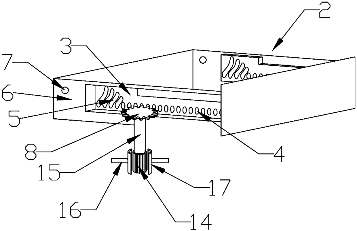
[0022] Such as figure 1 A switch cabinet drawer push-pull structure shown includes a cabinet body 1 and an installation drawer 2. The installation drawer 2 is equipped with electrical devices such as a circuit breaker and an isolating switch. The installation drawer 2 is slidably connected to the cabinet body 1. Both sides of the installation drawer 2 are provided with horizontal recessed grooves 3, and the recessed grooves 3 are inwardly recessed relative to the two sides 6 of the installation drawer, and a row of limiting holes 4 are provided on the two reces...


PUM


Abstract

A switch cabinet drawer push-pull structure includes cabinet body, mounting drawer, mounting drawer and cabinet body are slidably connected, two sides of mounting drawer are provided with a row of limit holes and arc-shaped strip holes, and two sides of mounting drawer are also provided with round holes on the inner side of both sides of mounting drawer. The two sides of the cabinet body are provided with a clamping part and a limiting part. The switch cabinet drawer push-pull structure of the invention can realize the clamping position of the mounting drawer through the clamping position part, so that the mounting drawer can be positioned and clamped at the required position. As that limit part is arranged, the mount drawer can be pulled out and tilted downward by a certain angle, and theelectric component inside the mounting drawer can be checked and operated more conveniently.

Description

technical field [0001] The invention relates to the field of switch cabinet equipment, in particular to a switch cabinet drawer push-pull structure. Background technique [0002] The main function of the switchgear is to open and close, control and protect electrical equipment during the process of power generation, transmission, distribution and power conversion in the power system. The general switchgear does not have a locking mechanism between the drawer unit and the cabinet body, and it is easy to slide when operating the electrical components in the drawer unit; when the drawer unit is pulled out to check the electrical components in the drawer unit, the current drawer It can only go straight in and out, which is not easy to operate. Contents of the invention [0003] The object of the present invention is to solve one of the above-mentioned problems. [0004] In order to achieve the above object, the present invention provides a switch cabinet drawer push-pull str...

Claims


Application Information

Patent Timeline
IPC IPC(8): H02B1/36
CPCH02B1/36
Inventor 赵成雷陈正茂张传荣
Owner 广东求精电气有限公司
Why Eureka
Try Eureka