A push-pull structure of a switch cabinet

A switchgear and cabinet door technology, applied to pull-out switchgear, switchgear, electrical components, etc., can solve the problems of drawers only going straight in and out, troublesome operation, easy to slide, etc., to achieve the effect of convenient inspection and operation

Active Publication Date: 2019-01-18
广东求精电气有限公司
View PDF11 Cites 1 Cited by
  • Summary
  • Abstract
  • Description
  • Claims
  • Application Information

AI Technical Summary

Problems solved by technology

When opening the door of a general switch cabinet, because the door is not fixed, it often swings and causes operational troubles, and there is no locking mechanism between the drawer unit and the cabinet body, it is easy to operate the electrical components in the drawer unit Sliding; when pulling out the drawer unit to check the electrical components in the drawer unit, the current drawer can only go straight in and out, and it is not easy to operate

Method used


Image

  • A push-pull structure of a switch cabinet
  • A push-pull structure of a switch cabinet
  • A push-pull structure of a switch cabinet

Examples


Embodiment Construction

[0023] Typical embodiments embodying the features and advantages of the present invention will be described in detail in the following description. It should be understood that the invention is capable of various changes in different embodiments without departing from the scope of the invention, and that the description and illustrations therein are illustrative in nature and not limiting. this invention.

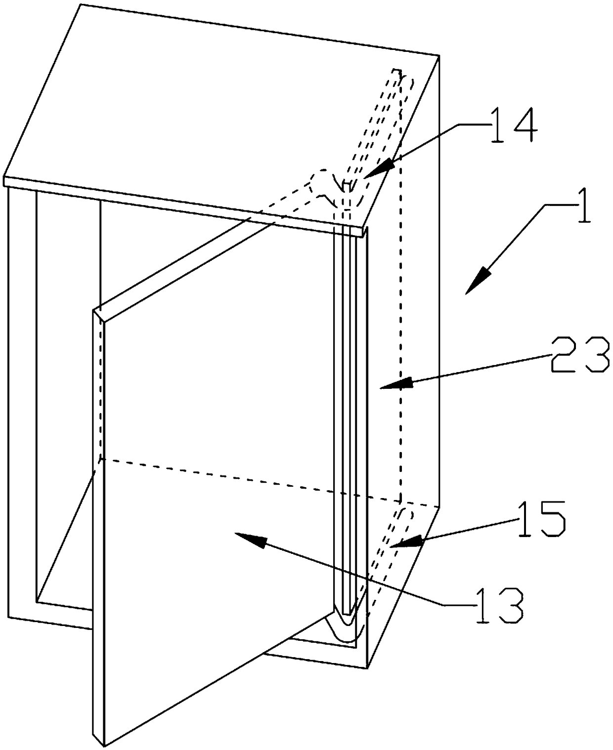
[0024] Such as figure 1 The push-pull structure of a switchgear shown includes a cabinet body 1, a cabinet door 13, and an installation drawer 2. The installation drawer 2 is equipped with electrical devices such as circuit breakers and isolating switches. The cabinet door 13 is rotatably connected to the cabinet On one side of the opening of the body 1, there is a cavity 23 outside the side where the cabinet body 1 is connected to the cabinet door 13, and the cavity 23 extends inward along the side of the cabinet body 1, and the installation drawer 2 Slidingly connected ...


PUM


Abstract

The invention discloses a push-pull structure of a switch cabinet, which comprises a cabinet body, a cabinet door and a mounting drawer, wherein the cabinet door is rotatably connected with one side of the cabinet body opening, the side the cabinet body connected with the cabinet door and is provided with a cavity, the mounting drawer is slidably connected with the cabinet body, the top plate andthe bottom plate of the cavity are respectively provided with an upper taxiway and a lower taxiway, and the cabinet door can slide along the upper taxiway and the lower taxiway; A row of limiting holes and arc-shaped strip holes are arranged on both sides of the mounting drawer, and round holes are arranged on the inner ends of the two sides of the mounting drawer; Both sides of the cabinet body are provided with clamping gears and limiting parts. The convex teeth of the clamping gear are inserted into the limiting hole, and the limiting part comprises a rotating rod, a limiting ball, a limiting lug and a telescopic shaft, wherein the telescopic shaft is telescopically inserted into the circular hole. The cabinet door can be hidden in the cabinet body, the mounting drawer can be clamped, the mounting drawer can be pulled out and tilted down by a certain angle, and the electric components inside the mounting drawer can be checked and operated more conveniently.

Description

technical field [0001] The invention relates to the field of switch cabinet equipment, in particular to a push-pull structure of a switch cabinet. Background technique [0002] The main function of the switchgear is to open and close, control and protect electrical equipment during the process of power generation, transmission, distribution and power conversion in the power system. When the door of the general switch cabinet is opened, the door is not fixed, so it often swings and causes trouble in operation, and there is no locking mechanism between the drawer unit and the cabinet body, it is easy to operate the electrical components in the drawer unit Sliding; when pulling out the drawer unit to check the electrical components in the drawer unit, the current drawer can only go straight in and out, and it is not easy to operate. Contents of the invention [0003] The object of the present invention is to solve one of the above-mentioned problems. [0004] In order to ac...

Claims


Application Information

Patent Timeline
Patent Type & Authority Applications(China)
IPC IPC(8): H02B11/173
CPCH02B11/173
Inventor 赵成雷陈正茂张传荣
Owner 广东求精电气有限公司
Why Eureka
Try Eureka