Aviation engine blade forging method and die

A technology of aero-engines and blades, which is applied in the direction of engine components, manufacturing tools, mechanical equipment, etc., can solve the problems of high production cost, complicated process, and large number of tooling, and achieve low production cost, simple process route, and air isolation. Effect

Active Publication Date: 2019-02-12
CHINA HANGFA SOUTH IND CO LTD
View PDF6 Cites 7 Cited by
  • Summary
  • Abstract
  • Description
  • Claims
  • Application Information

AI Technical Summary

Problems solved by technology

[0003] The invention provides an aeroengine blade forging method and a mold to solve the problems of the mainstream blade forging method, such as many fire times, a large number of tooling, complicated process and high production cost

Method used


Image

  • Aviation engine blade forging method and die
  • Aviation engine blade forging method and die
  • Aviation engine blade forging method and die

Examples


Embodiment Construction

[0024] It should be noted that the embodiments in the application and the features in the embodiments can be combined with each other if there is no conflict. Hereinafter, the present invention will be described in detail with reference to the drawings and in conjunction with the embodiments.

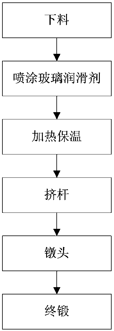
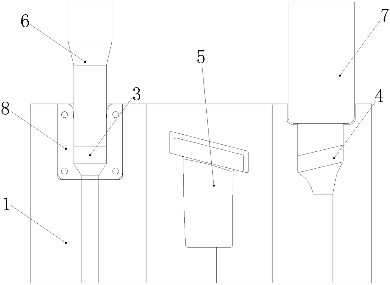
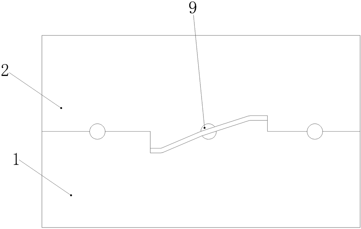
[0025] figure 1 It is a schematic flow chart of a forging method for an aeroengine blade according to a preferred embodiment of the present invention; figure 2 Is one of the schematic diagrams of the die for forging aeroengine blades according to the preferred embodiment of the present invention; image 3 It is the second schematic diagram of the die for forging aeroengine blades according to the preferred embodiment of the present invention.

[0026] Such as figure 1 As shown, the aeroengine blade forging method of this embodiment includes the following steps: a. blank blanking; b. spray glass lubricant on the surface of blank blank; c. heat blank blank to above the recrystallization tempe...


PUM

PropertyMeasurementUnit
thicknessaaaaaaaaaa

Abstract

The invention provides an aviation engine blade forging method and a die. The aviation engine blade forging method comprises the following steps that firstly, a blank is discharged; secondly, a glasslubricant is sprayed to the surface of the blank; thirdly, the blank is heated to the recrystallization temperature or above, and the temperature is kept; fourthly, the blank is put into a preheated extrusion cavity of the die, rod extruding is carried out, and an extrusion rod piece is obtained; fifthly, after rod extruding is completed, the extrusion rod piece is put into a heading cavity of thedie within 4 s-6 s, heading is carried out, and a heading piece is obtained; sixthly, after heading is completed, the heading piece is put into a finish forging cavity of the die within 4 s-6 s, final forging is carried out, and a blade is obtained. Due to the fact that the extrusion cavity, the heading cavity and the finish forging cavity are formed in the same die, the time interval between rodextruding and heading and the time interval between the heading and the finish forging are extremely short, the temperature of the extrusion rod piece and the temperature of the heading piece are reduced limitedly, and in the whole forging process, only one time of heating is needed for the blank.

Description

Technical field [0001] The invention relates to the technical field of forging of aeroengine blades, and in particular, to a forging method and die for aeroengine blades. Background technique [0002] The blade is a key component in an aero engine. The current mainstream blade forging method's technological process is: blanking→extrusion→upsetting→final forging. Among them, extruding rod, heading, and final forging are a single process, which needs to be carried out in three fire cycles, requiring three sets of molds and multiple equipment. There are many fires, a large number of tooling, complex process, and high production cost. Summary of the invention [0003] The invention provides an aeroengine blade forging method and a die, so as to solve the problems of the mainstream blade forging method of high frequency, large number of tooling, complex process and high production cost. [0004] The technical scheme adopted by the present invention is as follows: [0005] One aspect of...

Claims


Application Information

Patent Timeline
Patent Type & Authority Applications(China)
IPC IPC(8): B21J5/00B21J5/08B21J5/02B21J13/02B21K3/04
CPCB21J5/002B21J5/025B21J5/08B21J13/02B21K3/04
Inventor 彭谦之秦婷婷江杨辉隆如军李建军朴学华张强陈康陈有荣彭意志
Owner CHINA HANGFA SOUTH IND CO LTD
Why Eureka
Try Eureka