Control method and device for bidirectional rotary printing

A printing control and printing position technology, applied in the printing field, can solve the problems of left and right misalignment, blurred characters, indistinctness, etc., to achieve the effect of ensuring efficiency and improving printing speed

Active Publication Date: 2019-03-08
SHENZHEN HOSONSOFT CO LTD
View PDF7 Cites 6 Cited by
  • Summary
  • Abstract
  • Description
  • Claims
  • Application Information

AI Technical Summary

Problems solved by technology

[0004] The embodiment of the present invention provides a two-way rotary printing control method and device, which are used to solve the problems of blurred characters, unclear characters, and misalignment of left and right in PCB character printing in the prior art

Method used


Image

  • Control method and device for bidirectional rotary printing
  • Control method and device for bidirectional rotary printing
  • Control method and device for bidirectional rotary printing

Examples


Embodiment 1

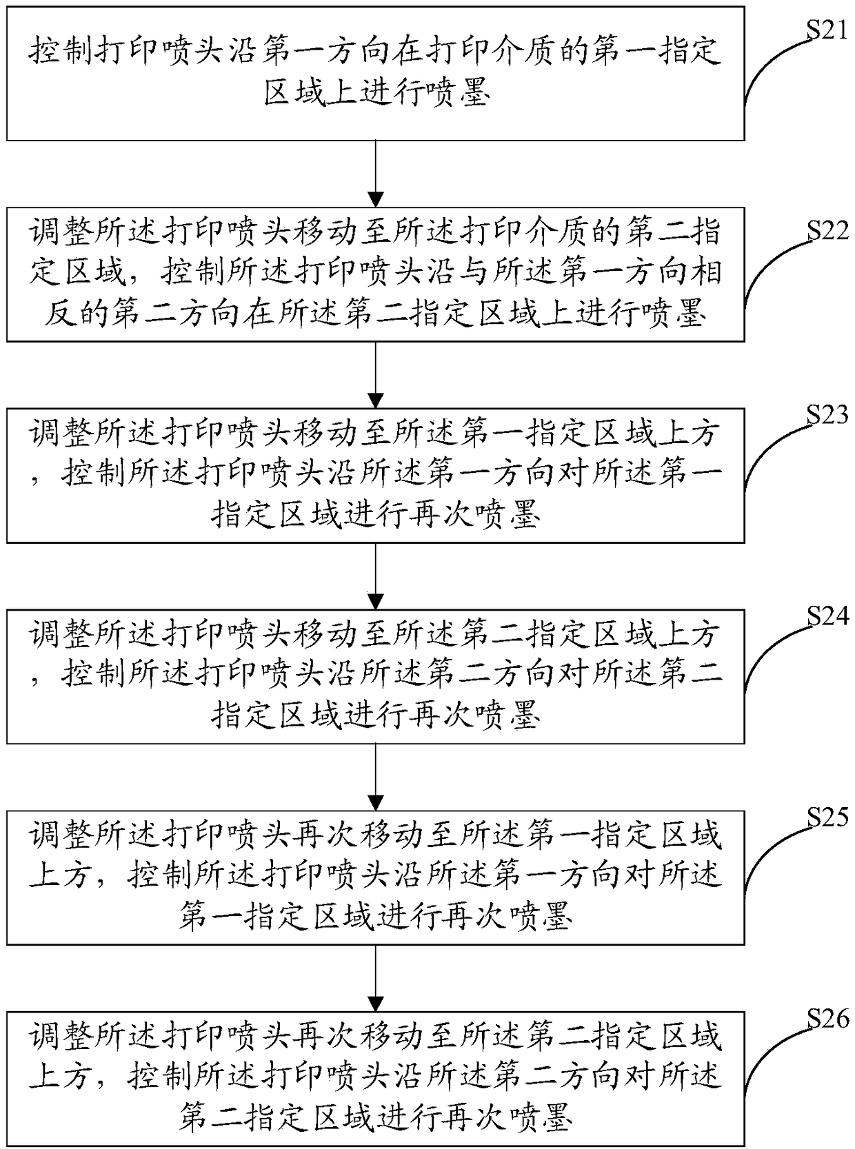
[0061] In this embodiment, each printing unit needs to cover 3 times, that is, 3pass printing, and the width of the first designated area perpendicular to the first direction is x 1 , the width of the print nozzle perpendicular to the first direction is x 2 , then x 1 =x 2 , the width of the pattern to be printed is twice the width of the nozzle along the first direction perpendicular to the first direction, that is, the image to be printed includes a first designated area and a second designated area, and the first designated area and the second designated area areas are adjacent, and the first specified area does not overlap with the second specified area, then refer to figure 2 , the specific printing steps of this embodiment are:

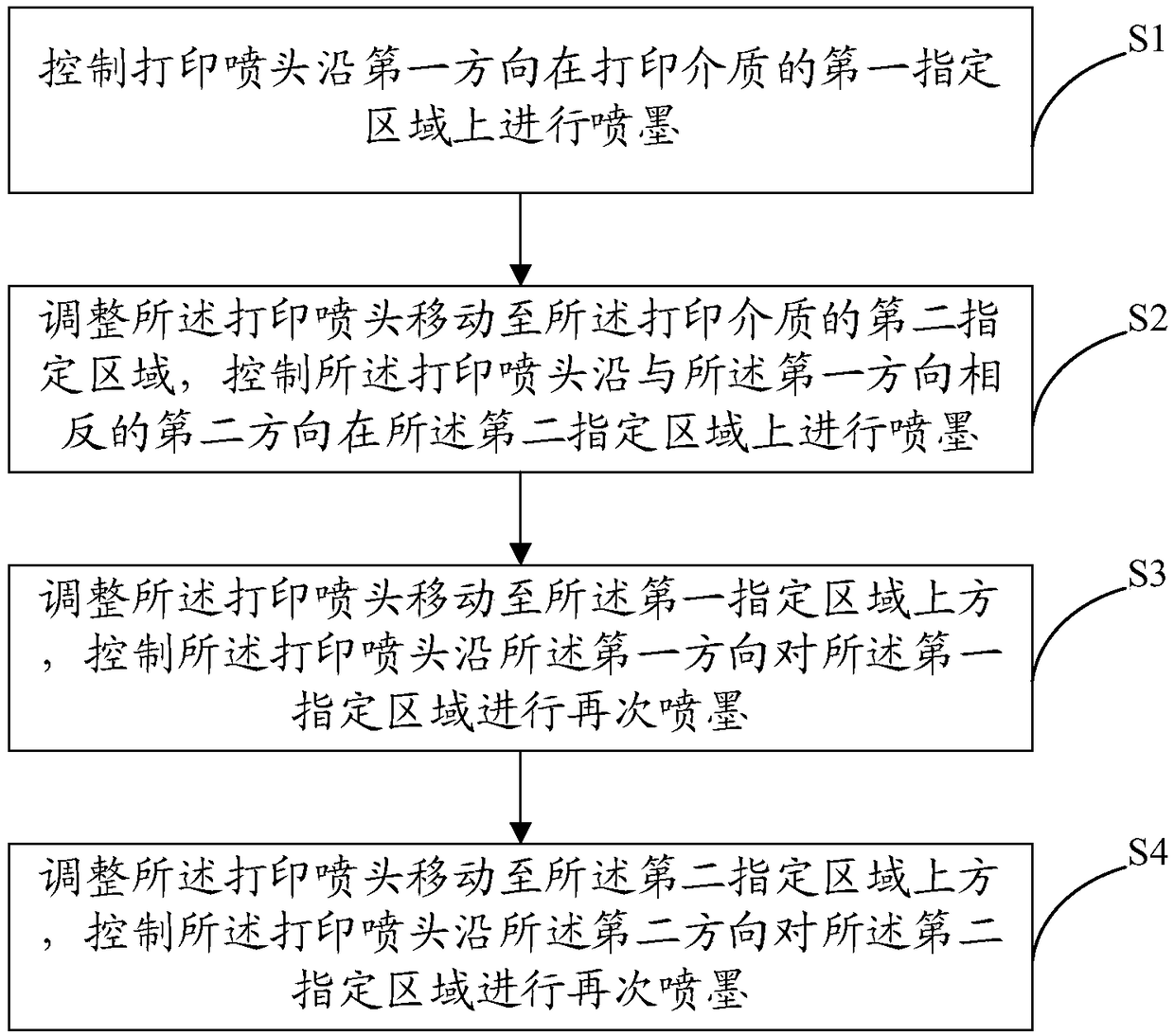
[0062] S21. Control the printing nozzle to spray ink on the first designated area of ​​the printing medium along the first direction;

[0063] S22. Adjust the print head to move to a second designated area of ​​the printing medium, and cont...

Embodiment 2

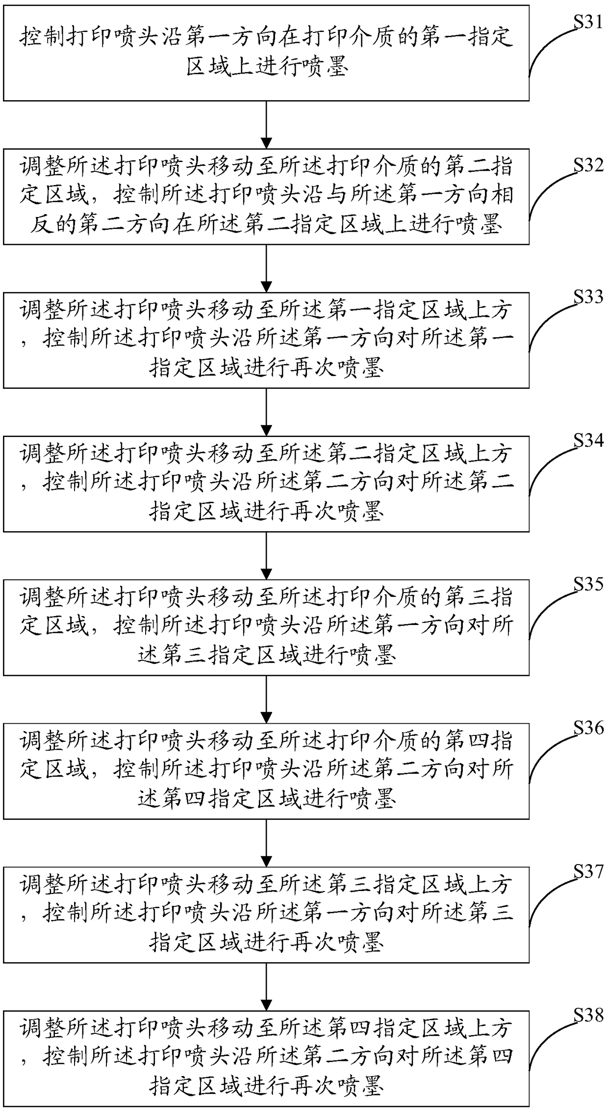
[0071] In this embodiment, each printing unit needs to cover 2 times, that is, 2pass printing, and the width of the first designated area perpendicular to the first direction is x 1 , the width of the print nozzle perpendicular to the first direction is x 2 , then x 1 =x 2 , the width of the pattern to be printed is 4 times the width of the nozzle along the vertical direction, that is, the image to be printed includes a first specified area, a second specified area, a third area and a fourth area. then see image 3 , the specific printing steps of this embodiment are:

[0072] S31. Control the printing nozzle to spray ink on the first designated area of ​​the printing medium along the first direction;

[0073] S32. Adjust the printing head to move to a second designated area of ​​the printing medium, and control the printing head to eject ink on the second designated area along a second direction opposite to the first direction;

[0074] S33. Adjust the printing head to m...

Embodiment 3

[0082] In this embodiment, each printing unit needs to cover 2 times, that is, 2pass printing, and the width of the first designated area perpendicular to the first direction is x 1 , the width of the print nozzle perpendicular to the first direction is x 2 , then x 1 =x 2 , the width of the pattern to be printed is three times the width of the nozzle along the vertical direction, that is, the image to be printed includes a first designated area, a second designated area and a fifth area. then see Figure 5 , the specific printing steps of this embodiment are:

[0083] S51. Control the printing nozzle to spray ink on the first designated area of ​​the printing medium along the first direction;

[0084] S52. Adjust the print head to move to a second designated area of ​​the printing medium, and control the print head to eject ink on the second designated area along a second direction opposite to the first direction;

[0085] S53. Adjust the printing head to move above the ...


PUM


Abstract

The invention discloses a control method and a device for bidirectional rotary printing. The control method for the bidirectional rotary printing includes the following steps of 1, controlling a printing head to conduct ink jetting on a first designated area of printing medium in a first direction; 2, adjusting the printing head to move to a second designated area of the printing medium and controlling the printing head to conduct the ink jetting on a second designated area in a second direction opposite to the first direction; 3, adjusting the printing head to move to a position above the first designated area and controlling the printing head to conduct the ink jetting on the first designated area in the first direction again; and 4, adjusting the printing head to move to a position above the second designated area and controlling the printing head to conduct ink jetting on the second designated area in the second direction again, wherein the second designated area is not overlappedwith the first designated area. According to the control method and the device for the bidirectional rotary printing, definition of printed characters is ensured and the bidirectional printing of adjacent regions ensures printing efficiency.

Description

technical field [0001] The invention relates to the field of printing technology, in particular to a method and device for controlling bidirectional rotary printing. Background technique [0002] Printed circuit board (PCB, printed circuit board), also known as printed circuit board or printed circuit board, is based on an insulating board, cut to a certain size, and printed some lines, pads / vias on it , solder resist, characters and some conductive graphics to realize the interconnection between electronic components. [0003] The characters displayed on the PCB board are usually printed with white ink. White ink is prone to problems such as blurring and indistinctness. Therefore, PCB character printers usually use one-way printing to meet the printing effect requirements. Specifically, the printer only prints in one direction. Printing, but the printing speed is slow and the efficiency is low. In order to improve printing efficiency, adopting bidirectional printing is th...

Claims


Application Information

Patent Timeline
Patent Type & Authority Applications(China)
IPC IPC(8): B41M5/00B41J2/01
CPCB41J2/01B41M5/0047
Inventor 苏树波黄振金陈艳
Owner SHENZHEN HOSONSOFT CO LTD
Why Eureka
Try Eureka