
A Method of On-line Monitoring Mechanism Spring of High Voltage Circuit Breaker Using Load Cell
A force sensor and high-voltage circuit breaker technology, which is applied to circuits, components of protective switches, and switchgear status indicators, etc., can solve problems such as aging deformation of contact springs, circuit breaker failures, and affecting power transmission in the power grid.
- Summary
- Abstract
- Description
- Claims
- Application Information
AI Technical Summary
Problems solved by technology
Method used
Image

Examples
Embodiment
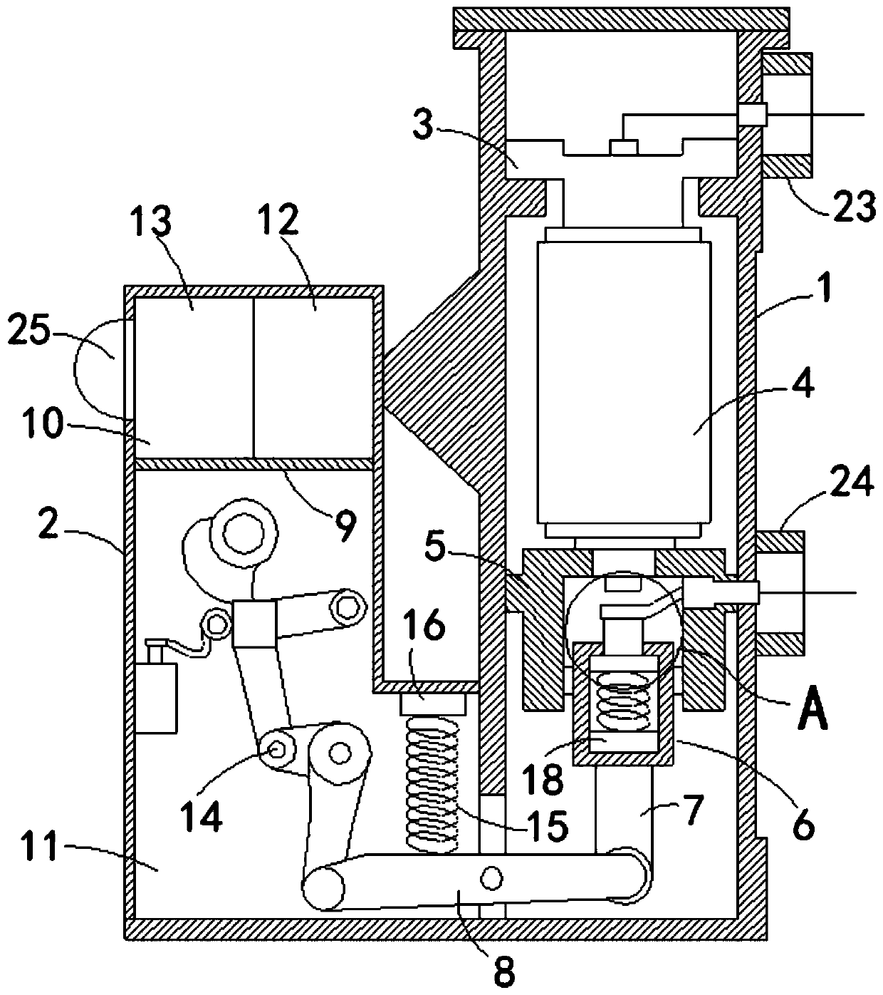
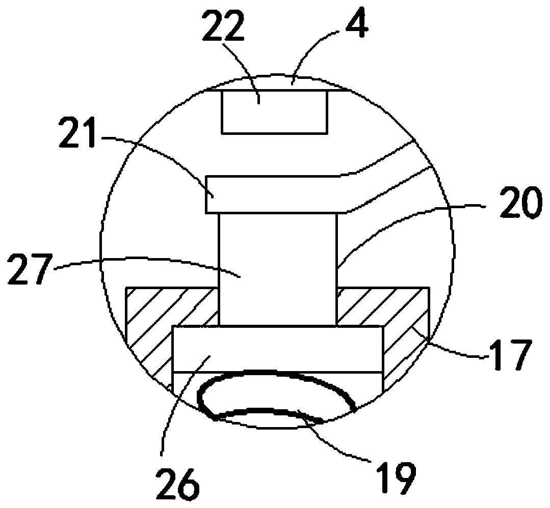
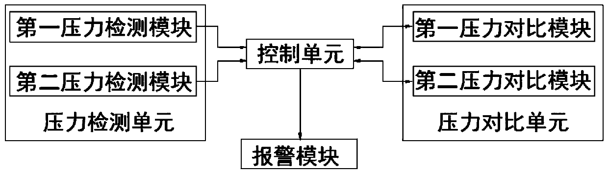
[0023] refer to Figure 1-3 , a method for online monitoring of the mechanism spring of a high-voltage circuit breaker with a load cell. The circuit breaker includes a main case 1 and an auxiliary case 2 connected at its front end and connected to its interior. The main case 1 is sequentially arranged from top to bottom. There are upper support 3, vacuum interrupter 4, lower support 5, opening and closing mechanism 6, insulating pull rod 7 and rotating rod 8. It is worth mentioning that the sub-housing 2 is divided into a control room 10 by a horizontal partition 9 and control room 11.
[0024] The sub-housing 2 is divided into a control room 10 and an operating room 11 by a partition 9 arranged horizontally. A controller 12 and an alarm 13 are installed in the control room 10. Specifically, the alarm 13 includes an alarm lamp 25 arranged at its front end , and the alarm 13 runs through the sub-housing 2 and extends to the outside of it, and uses sound and light to alarm, whi...
PUM
 Abstract
Description
Claims
Application Information