Radar module

A technology of radar and radar signals, which is applied to antennas, instruments, and devices for manufacturing antenna arrays, and can solve problems such as high integration of difficult technologies

Active Publication Date: 2019-04-16
NXP USA INC
View PDF9 Cites 2 Cited by
  • Summary
  • Abstract
  • Description
  • Claims
  • Application Information

AI Technical Summary

Problems solved by technology

It is difficult to achieve a high degree of integration of said technology in a small space without limiting the functionality of this technology

Method used


Image

  • Radar module
  • Radar module
  • Radar module

Examples


Embodiment Construction

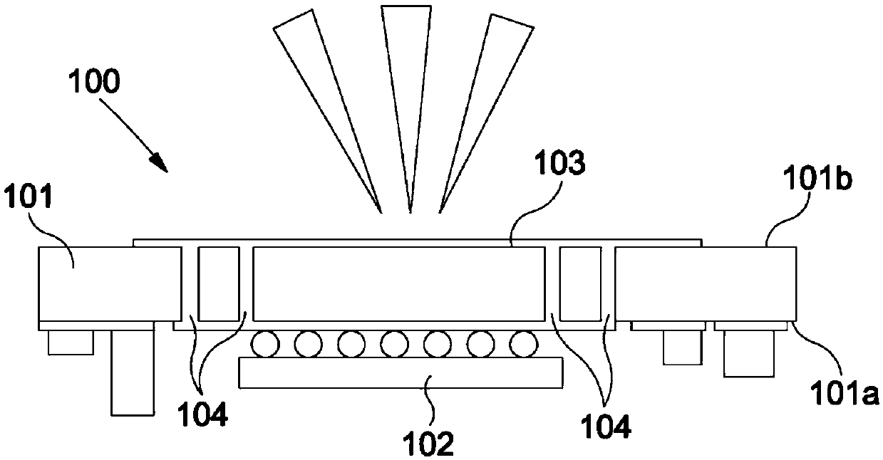
[0028] figure 1 An example radar module 100 is shown. The figure shows a cross-section of the module 100 . Module 100 includes a low temperature co-fired ceramic (LTCC) substrate 101 having a first surface 101a and an opposite second surface 101b. The radar chip 102 is attached to the first surface 101a of the LTCC substrate 101 (eg, by solder joints). Radar chip 102 is an integrated circuit containing the electronics needed to generate and process radar signals. For example, radar chip 102 may include a radar front end and a radar microcontroller.

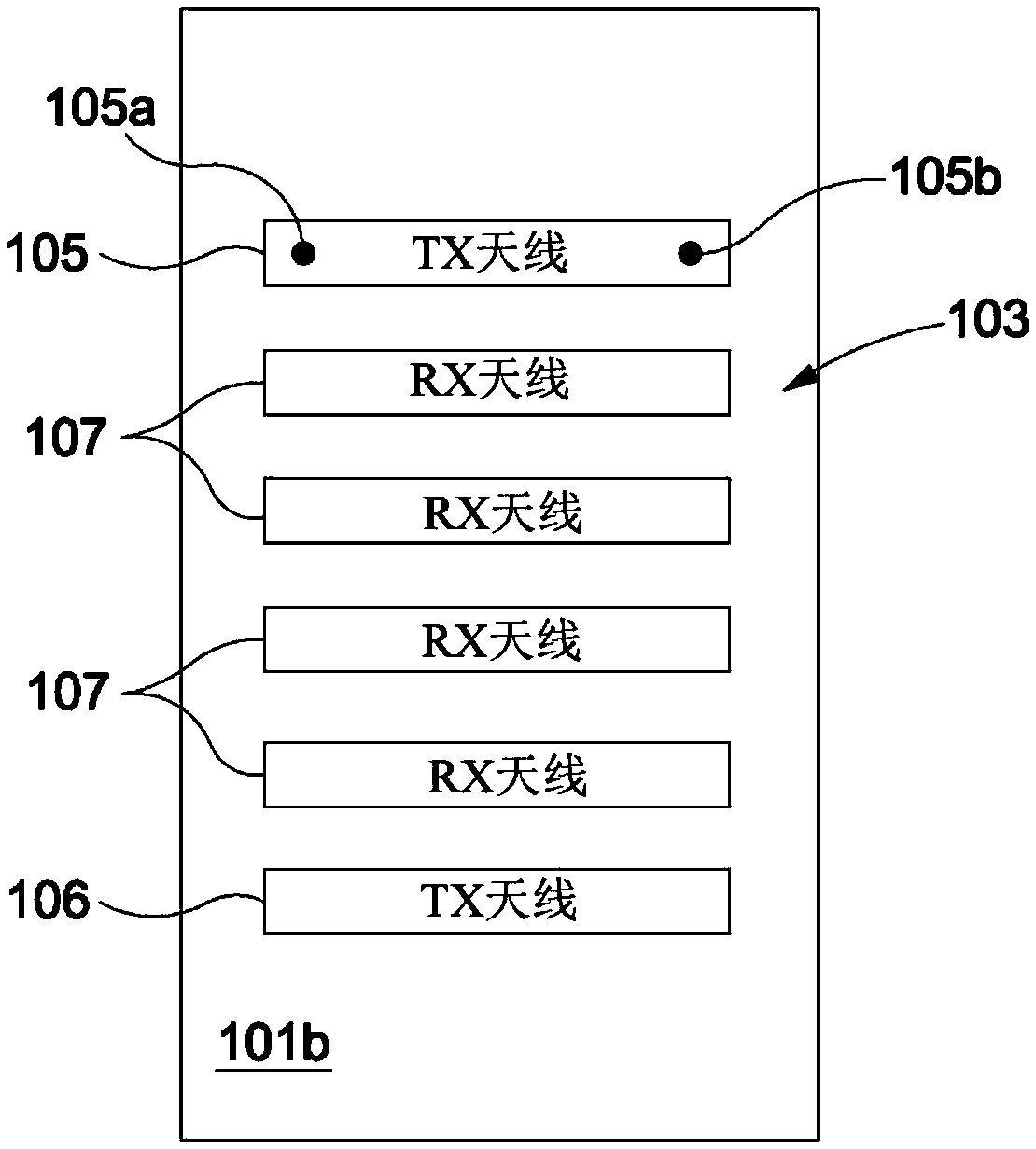
[0029] The antenna array 103 is attached to the opposite second surface 101b of the substrate 101 . The antenna array 103 is adapted to transmit the radar signal generated by the radar chip 102 (shown as the transmission triangle in said figure). The signal is transmitted from the radar chip 102 to the transmitting antenna of the antenna array 103 via the connection 104 ( figure 2 shown). Connections 104 may include conduc...


PUM


Abstract

The invention relates to a radar module. The radar module (100; 200) comprises a low temperature co-fired ceramic, LTCC, substrate (101; 201), with a radar chip (102; 202) attached to a first surface(101a; 201a) of the LTCC substrate (101; 201) and a transmitting antenna (105, 106) for transmitting the radar signal attached to a second surface (101b; 201b) of the LTCC substrate (101; 201). The radar chip (102; 202) is configured to generate a radar signal for transmission. The transmitting antenna (105, 106) is configured to communicate with the radar chip (102; 202) through the LTCC substrate (101; 201). The radar module (100; 200) further comprises a beam steering element (205) configured to introduce a phase delay to the radar signal in order to adjust a first component of a directionof transmission of the radar signal.

Description

technical field [0001] The present disclosure relates to radar modules, eg, millimeter wave radar modules. Background technique [0002] Especially for automotive applications, it is desirable to minimize the size and cost of radar modules. However, radar modules combine multiple technologies with different performance characteristics. It is difficult to achieve a high degree of integration of such technologies in a small space without limiting the functionality of such technologies. Contents of the invention [0003] According to a first aspect of the present disclosure, there is provided a radar module comprising: a low temperature co-fired ceramic LTCC substrate; a radar chip attached to a first surface of the LTCC substrate and configured to generate a radar signal for transmission and a transmitting antenna for transmitting the radar signal, the transmitting antenna attached to the second surface of the LTCC substrate and configured to communicate with the radar chi...

Claims


Application Information

Patent Timeline
Patent Type & Authority Applications(China)
IPC IPC(8): G01S7/02G01S13/931
CPCG01S7/02H01Q3/40H01Q21/0093H01Q23/00G01S7/032G01S13/931H01Q3/34
Inventor A·锡安R·罗伊特S·艾哈迈德E·塞勒
Owner NXP USA INC
Why Eureka
Try Eureka