Fabric humidifier for spinning machinery

A technology of textile machinery and humidifier, which is applied to the processing of textile material drums, equipment configuration for processing textile materials, spraying/spraying of textile materials, etc. It can solve the problems of inconvenient ironing, large manpower consumption, and uniform moisture, and achieve overall The structural design is compact and reasonable, reducing the loss of energy consumption and the effect of reducing mechanical noise

Active Publication Date: 2019-05-03
朱泽鹏
View PDF6 Cites 2 Cited by
  • Summary
  • Abstract
  • Description
  • Claims
  • Application Information

AI Technical Summary

Problems solved by technology

[0004] In the prior art, the method of artificial humidification is usually adopted, which consumes a lot of manpower and is ineffective; it is also possible to use the method of machine humidification, but it is difficult to make the moisture even, and uneven water is not conducive to ironing, and Existing machine humidification generally performs humidification on the top surface of the cloth, resulting in obvious differences in the humidity of the upper and lower sides of the cloth after humidification, which is not convenient for subsequent ironing.

Method used


Image

  • Fabric humidifier for spinning machinery
  • Fabric humidifier for spinning machinery
  • Fabric humidifier for spinning machinery

Examples


Embodiment Construction

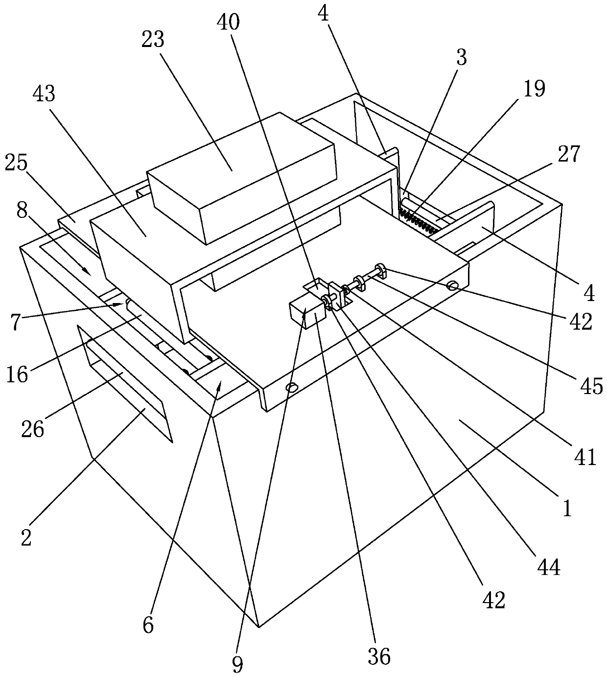
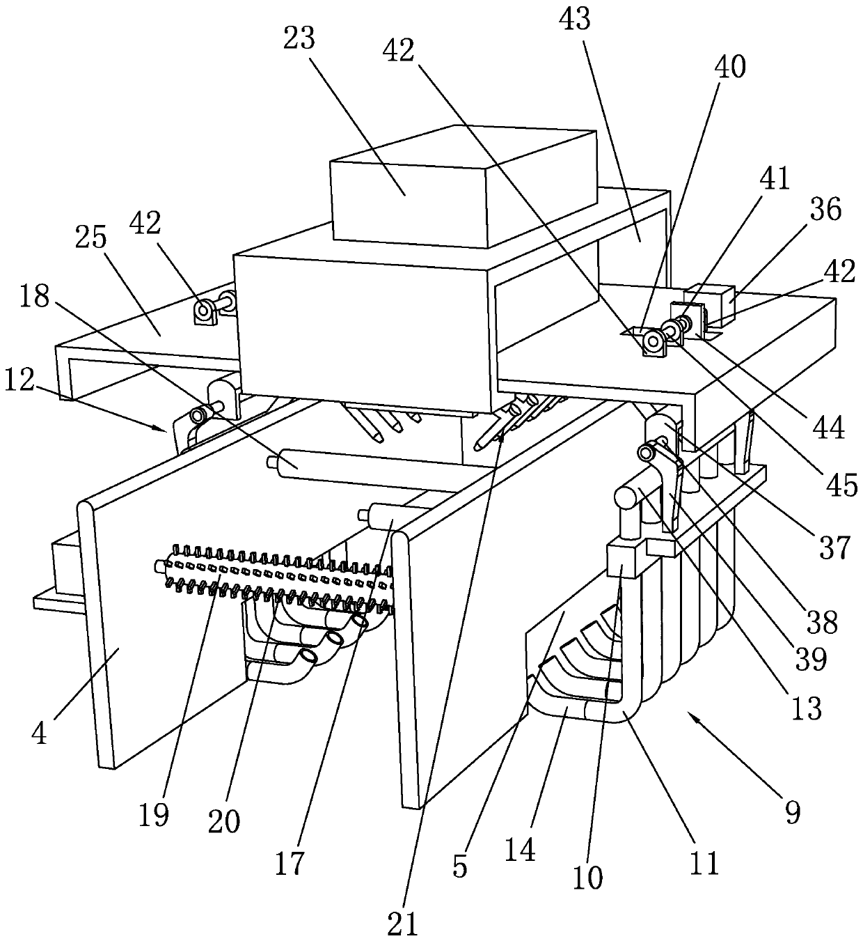
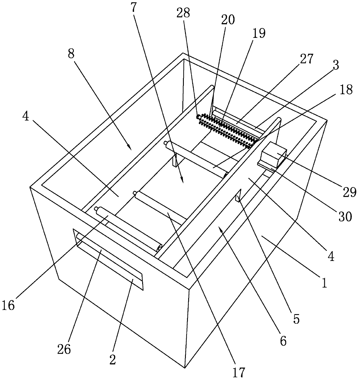
[0027] Such as Figure 1 to Figure 5 As shown, it is a fabric humidifier for textile machinery according to the present invention, which includes a box body 1, the left end of the box body 1 is provided with a cloth inlet groove 2, the right end of the box body 1 is provided with a cloth outlet groove 3, and the cloth inlet groove 2 is provided with There is a cloth feeding roller 26, and a cloth feeding roller 27 is arranged in the cloth outlet trough 3. The design of the cloth feeding roller 26 is more convenient for the cloth to enter the box body 1 for humidification treatment, and prevents the cloth from entering the box body 1. Friction occurs on the side wall of the cloth, and the design of the cloth roller 27 can facilitate the output of the cloth from the casing 1, and avoid friction with the side wall of the cloth outlet trough 3 when the cloth is output from the casing 1.

[0028] There are two spacers 4 arranged horizontally and symmetrically in the box body 1. The...


PUM


Abstract

The invention discloses a fabric humidifier for spinning machinery. The fabric humidifier comprises a box, two space plates are symmetrically and horizontally arranged in the box, and the interior ofthe box is divided into a front cavity, a middle cavity and a rear cavity through the two space plates; bottom spray rod assemblies are arranged in the front cavity and the rear cavity, the middle cavity corresponds to a fabric inlet groove and a fabric outlet groove, and a first fabric guide roller, a tension roller, a second fabric guide roller and a vibration roller are arranged in the middle cavity from left to right in sequence; a top spray rod assembly is arranged over the tension roller. According to the fabric humidifier for spinning machinery, through the top spray rod assembly and the bottom spray rod assemblies, the upper and lower faces of the fabric are humidified at the same time, compared with humidification only on one face of the fabric in the prior art, the whole fabric is more evenly humidified, more convenience is provided for following ironing operation on the fabric, based on the actual conveying angle and speed of the fabric, the angle is adjusted through the bottom spray rod assemblies, the humidification condition of the bottom face of the fabric is guaranteed, and the processing quality of the fabric in the later period is improved.

Description

technical field [0001] The invention relates to a fabric humidifier for textile machinery. Background technique [0002] Textile industry in our country is a highly labor-intensive and foreign-dependent industry. my country is the world's largest producer and exporter of textiles and clothing. The sustained and stable growth of textiles and clothing exports is crucial to ensuring my country's foreign exchange reserves, balance of payments, stability of the RMB exchange rate, social employment and sustainable development of the textile industry. [0003] Ironing is an essential process in the textile process. Its purpose is to remove the wrinkles produced in the previous processing. High temperature is required in the ironing process, but temperature alone is not enough. Too high temperature will easily damage the fabric. Ironing, only relying on moisture can make the heat energy quickly enter the fiber, realize the rapid heat transfer, shorten the heating time, reduce its y...

Claims


Application Information

Patent Timeline
Patent Type & Authority Applications(China)
IPC IPC(8): D06B1/02D06B23/02D06B23/20D06B15/06
Inventor 赵城
Owner 朱泽鹏
Why Eureka
Try Eureka