Clutch mechanism

A clutch mechanism and clutch piece technology, applied in the field of transmission, can solve problems such as user obstacles, user injuries, and inability to guarantee stability, and achieve the effects of smooth use, enhanced stability, and uniform distribution of meshing force

Pending Publication Date: 2019-05-03
HANGZHOU SUKONG SOFTWARE CO LTD
View PDF1 Cites 1 Cited by
  • Summary
  • Abstract
  • Description
  • Claims
  • Application Information

AI Technical Summary

Problems solved by technology

[0004] The clutch device used between the wheel core and the pulley in this utility model can realize the transmission connection or mutual disengagement between the wheel core and the pulley according to the needs, but the clutch device cannot guarantee the stability of these

Method used


Image

  • Clutch mechanism
  • Clutch mechanism
  • Clutch mechanism

Examples


Embodiment Construction

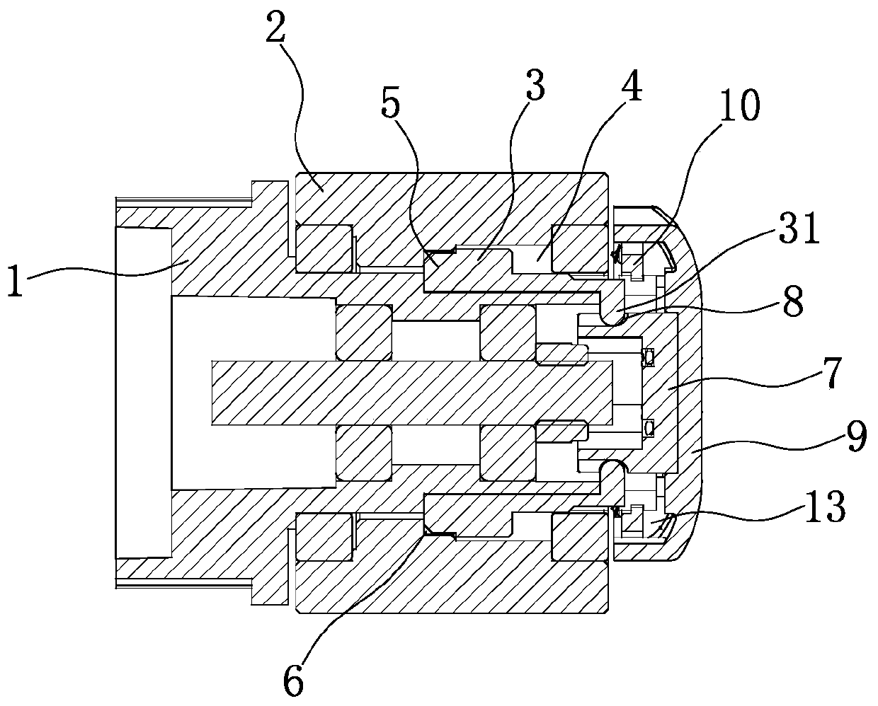
[0026] The present invention will be described in further detail below in conjunction with the accompanying drawings and specific embodiments.

[0027] Such as figure 1 As shown, a clutch mechanism includes a first rotating member 1, and a second rotating member 2 that is axially positioned and circumferentially rotatably connected is sleeved on the periphery of the first rotating member 1, and is characterized in that the first rotating member A controlled clutch structure is provided on a rotating member 1 or a second rotating member 2, and when the controlled clutch structure operates, the second rotating member 2 can be positioned circumferentially relative to the first rotating member 1 or the second rotating member can be 2 is rotatable in the circumferential direction relative to the first rotating member 1, and the above-mentioned controlled clutch structure is provided with a clutch state locking structure.

[0028] The first rotating part 1 and the second rotating p...


PUM


Abstract

The invention belongs to the technical field of transmission, specifically a clutch mechanism. The clutch mechanism provided by the invention comprises a first rotating part, wherein a second rotatingpart which is axially positioned and rotationally connected in a circumferential direction is sleeved on the periphery of the first rotating part; the first rotating part or the second rotating partis provided with a controlled clutch structure; when the controlled clutch structure acts, the second rotating part can be circumferentially positioned relative to the first rotating part or the second rotating part can rotate circumferentially relative to the first rotating part; and the controlled clutch structure is provided with a clutch state locking structure. According to the invention, theclutch state locking structure is arranged between the two rotating parts, so that the stable state can be maintained when the two rotating parts are in a transmission connection state or are separated from each other, and switching between the two states cannot be easily caused by some accidental external factors, so as to ensure smooth use of products provided with the clutch mechanism and prevent accidents causing injuries to users.

Description

technical field [0001] The invention belongs to the technical field of transmission, and in particular relates to a clutch mechanism. Background technique [0002] The clutch mechanism is a commonly used structure in the mechanical transmission process, which can selectively realize the transmission connection or mutual separation between two different parts, so as to meet the different needs of users in different usage scenarios. [0003] For example, a Chinese utility model patent discloses a driving wheel for an electric scooter [application number: 201720468425.4]. The utility model patent includes a tire, a wheel core and a pulley on one side of the wheel core. A clutch device is provided between the pulleys, and the clutch device can drive the wheel core to be connected or separated from the pulley. The clutch device includes an end gear. The top half cylinder; the left side of the pulley is provided with slopes corresponding to the inclined top surfaces of the half c...

Claims


Application Information

Patent Timeline
IPC IPC(8): F16D11/14F16D23/12
Inventor 朱筱凯
Owner HANGZHOU SUKONG SOFTWARE CO LTD
Why Eureka
Try Eureka